74HCT534N 데이터 시트보기 (PDF) - NXP Semiconductors.
부품명
상세내역
제조사
74HCT534N Datasheet PDF : 15 Pages
| |||
Philips Semiconductors
74HCT534
5 V octal D-type flip-flop; positive-edge trigger; inverting; 3-state
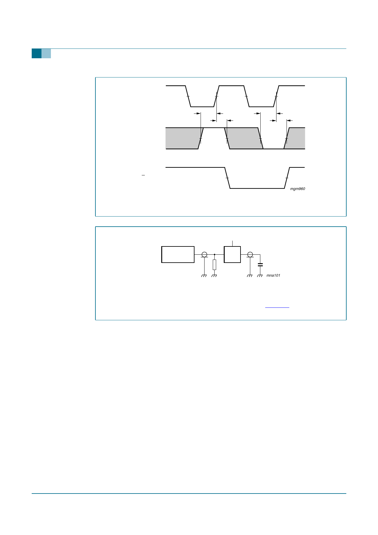
CP input
Dn input
VM
tsu
th
VM
tsu
th
Qn output
VM
mgm960
VM = 1.3 V; VI = GND to 3 V.
Fig 8. Waveforms showing the data set-up and hold times for Dn input.
PULSE
VI
GENERATOR
VCC
VO
D.U.T.
RT
CL
mna101
Fig 9.
Definitions test circuits:
RT = Termination resistance should be equal to output impedance Zo of the pulse generator.
CL = Load capacitance including jig and probe capacitance (See Section 11 for the value).
Load circuitry for switching times.
9397 750 13817
Product data sheet
Rev. 03 — 18 October 2004
© Koninklijke Philips Electronics N.V. 2004. All rights reserved.
10 of 15
Share Link: 