ELM413 데이터 시트보기 (PDF) - Elm Electronics
부품명
상세내역
제조사
ELM413 Datasheet PDF : 4 Pages
| |||
ELM413
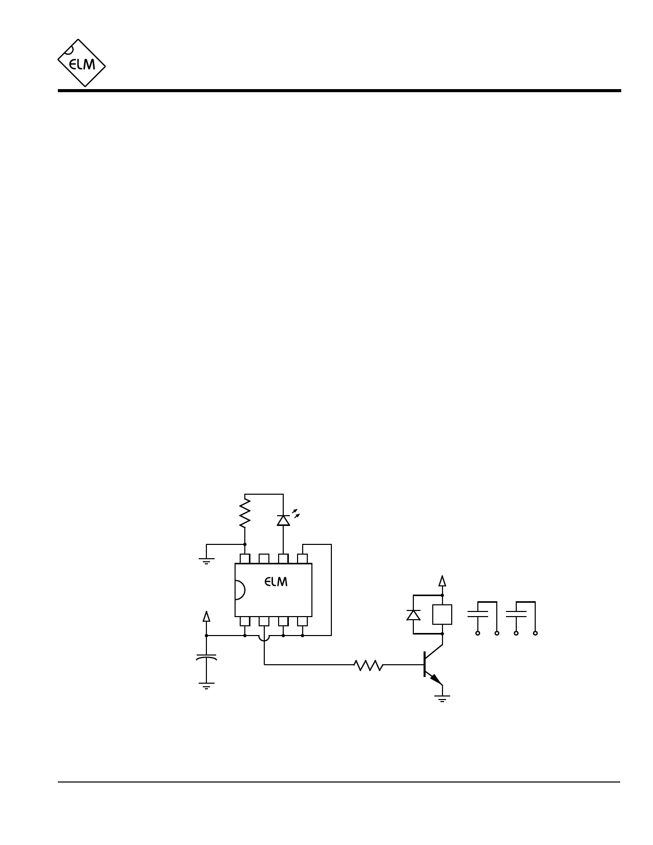
Example Application
Figure 1 below shows the ELM413 used in a
typical speaker control and pilot lamp circuit for an
audio amplifier. In this instance, the majority of the
circuit components required are associated with
the relay that is used to block the speaker outputs
until the power has stabilized.
For this application, W0 and W1 are both tied
to a logic high level, so the warmup period is
selected to be 5 seconds. This is likely a good
choice for most circuits of this type, although some
may be able to use the 1 second setting.
The ELM413 has its trigger pin connected
directly to Vdd, causing the circuit to sequence
whenever the power is turned on. If the trigger
input should be connected to another voltage
source, keep in mind that a series resistor should
always be used. The resistor limits current flow
when either supply is at a different level than the
other. Typical values would be about 100KΩ, so
that the input current shown under the Electrical
Characteristics section is not exceeded.
Only one LED is used for this circuit, as a red
LED would never be lit in this instance. Other
applications may require that both red and green
LEDs be used, and the ELM413 adapts easily to
this as it has separate outputs for both. The
outputs can easily drive back to back two wire
LEDs as well as the common cathode three wire
types, and of course, discrete diodes. As the red
and green outputs are not active at the same time,
a single series current limiting resistor is usually all
that is required.
The circuit shown below causes the green
LED to flash for 5 seconds, followed by a steady
output. If one wanted a solid output without
flashing, the LED could have been connected
directly to VDD, or it could have been connected
from VDD to pin 7 of the ELM413 (with a series
resistor). The latter case would likely be needed
for circuits that are retriggered using pin 5, without
the power being cycled.
The ELM413 is a simple yet versatile circuit
that is convenient and easy to use. Other uses
would include generating pulses from a trigger
input, or connecting several in series to generate
sequential events…
270Ω
Green
LED
8765
413
+5V
1234
0.1µF
1N4001
+12V
12V Relay
2.2KΩ
2N3904
L
R
Speaker
Enable
ELM413DSA
Figure 1. Typical Speaker Control Circuit
Elm Electronics – Circuits for the Hobbyist
< http://www.elmelectronics.com/ >
4 of 4
Share Link: 