HMS81016E 데이터 시트보기 (PDF) - Hynix Semiconductor
부품명
상세내역
제조사
HMS81016E Datasheet PDF : 77 Pages
| |||
HMS81004E/08E/16E/24E/32E
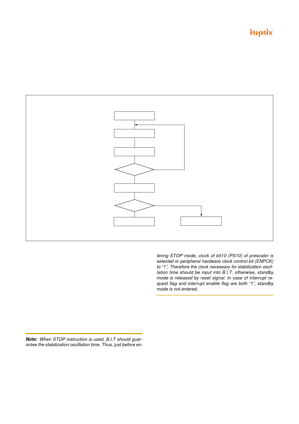
15.4 RELEASE OPERATION OF STANDBY MODE
After standby mode is released, the operation begins ac-
cording to content of related interrupt register just before
standby mode start (Figure 15-3).
STOP Command
Standby Mode
Interrupt Request GEN.
0
Int. enable reg.
1
Standby Mode Release
PSW
0
I Flag
1
Interrupt Service Routine
Standby Next Command
Execution
.
Figure 15-3 Standby Mode Release Flow
(1) Interrupt Enable Flag(I) of PSW = “0”
Release by only interrupt which interrupt enable flag =
“1”, and starts to execute from next to standby instruction
(SLEEP or STOP).
tering STOP mode, clock of bit10 (PS10) of prescaler is
selected or peripheral hardware clock control bit (ENPCK)
to “1”, Therefore the clock necessary for stabilization oscil-
lation time should be input into B.I.T. otherwise, standby
mode is released by reset signal. In case of interrupt re-
quest flag and interrupt enable flag are both “1”, standby
mode is not entered.
(2) Interrupt Enable Flag(I) of PSW = “1”
Released by only interrupt which each interrupt enable flag
= “1”, and jump to the relevant interrupt service routine.
Note: When STOP instruction is used, B.I.T should guar-
antee the stabilization oscillation time. Thus, just before en-
58
JUNE 2001 Ver 1.00
Share Link: 