HMS97C8032 데이터 시트보기 (PDF) - Hynix Semiconductor
부품명
상세내역
제조사
HMS97C8032 Datasheet PDF : 157 Pages
| |||
HMS91C8032/97C8032
2. MEMORY ORGANIZATION
All HMS91C8032 devices have separate address spaces for pro-
gram and data memory. The logical separation of program and
data memory allows the data memory to be accessed by 8-bit ad-
dresses, which can be quickly stored and manipulated by an 8-bit
CPU.
Program memory (ROM) can only be read, not written to. There
can be up to 32K bytes of program memory. In the
HMS9XC8032 devices, the Program Memory is provided
on-chip.
Data Memory (RAM) occupies a separate address space from
Program Memory. In the HMS9XC8032, the data memory is
on-chip.
2.1 Program Memory
Figure 2-1 shows a map of the lower part of the Program Memo-
ry. After reset, the CPU begins execution from location 0000H.
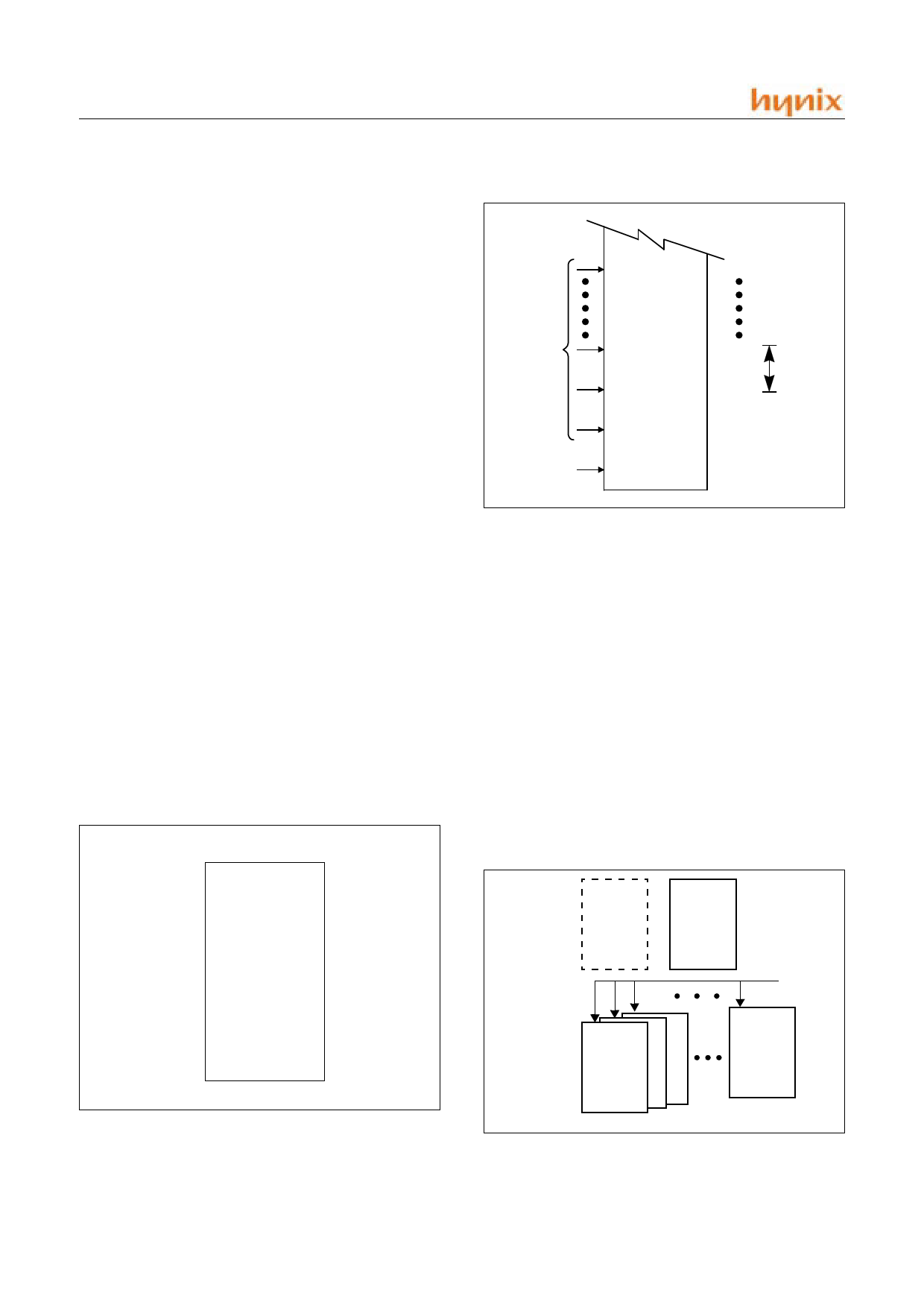
As shown in Figure 2-2, each interrupt is assigned a fixed loca-
tion in Program Memory. The interrupt causes the CPU to jump
to that location, where it commences execution of the service rou-
tine. External Interrupt 0, for example, is assigned to location
0003H. If External Interrupt 0 is going to be used, its service rou-
tine must begin at location 0003H. If the interrupt is not going to
be used, its service location is available as general purpose Pro-
gram Memory.
The interrupt service locations are spaced at 8-byte intervals :
0003H for External Interrupt 0, 000BH for Timer 0, 0013H for
External Interrupt 1, 001BH for Timer 1 and etc. If an interrupt
service routine is short enough (as is often the case in control ap-
plications), it can reside entirely within that 8-byte interval.
Longer service routines can use a jump instruction to skip over
subsequent interrupt locations, if other interrupts are in use.
Program Memory addresses are always 16bits wide, even though
the actual amount of Program Memory used may be less than 32K
bytes.
7FFFH
32Kbyte
0000H
Figure 2-1 Program Mamory
008BH
Interrupt
Location
Reset
0013H
000BH
8 Bytes
0003H
0000H
Figure 2-2 Interrupt Location of Program Memory
2.2 Data Memory
Figure 2-3, Figure 2-6 and Figure 2-6 shows the Memory spaces
available to the HMS9XC8032 user. HMS9XC8032 can address
up to 1kbytes of data memory. 10bits address is configured as fol-
lows.
10bits address for READ memory operation = 2bits of RDPG +
8bits of implied address in instruction
10bits address for WRITE memory operation = 2bits of WRPG +
8bits of implied address in instruction
(Where, 0 =< RDPG, WRPG =< 6)
(CAUTIONS: A valid value which can be stored in RDPG and
WRPG must be from 0 to 6. 7 is reserved for indirect addressable
memory region.(upper 128bytes region) A programmer who set
RDPG/WRPG to 7 or greater than 7 will get the invalid memory
operation results. )
7FH
Upper
128
00H
Accessible
by Indirect
Addressing
Only
7FH
Lower
128
Accessible
by Direct
Addressing
00H
Accessible
by Direct
Addressing
RDPG
WRPG
Accessible
by Direct
Addressing
Figure 2-3 Data Memory Structure
6
NOV., 2001 Ver 1.02
Share Link: 