223AT 데이터 시트보기 (PDF) - Vishay Semiconductors
부품명
상세내역
제조사
223AT
Vishay Semiconductors

223AT Datasheet PDF : 7 Pages
| |||
IL221AT/222AT/223AT
Optocoupler, Photodarlington Output, Vishay Semiconductors
Low Input Current, High Gain, with Base
Connection
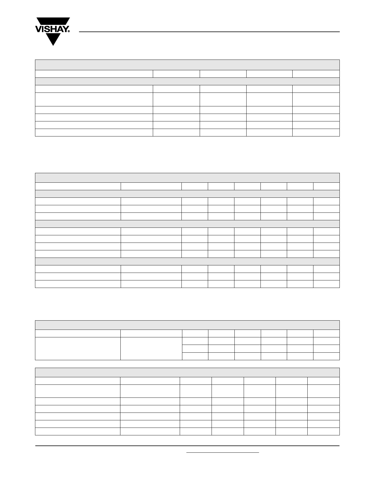
ABSOLUTE MAXIMUM RATINGS
PARAMETER
TEST CONDITION
SYMBOL
VALUE
UNIT
COUPLER
Isolation test voltage
Total package dissipation
(at 25 °C ambient)(LED and detector)
t = 1.0 s
VISO
Ptot
4000
240
VRMS
mW
Derate linearly from 25 °C
3.2
mW/°C
Storage temperature
Operating temperature
Soldering time at 260 °C
Tstg
- 55 to + 150
°C
Tamb
- 55 to + 100
°C
10
s
Note
Tamb = 25 °C, unless otherwise specified.
Stresses in excess of the absolute maximum ratings can cause permanent damage to the device. Functional operation of the device is not implied
at these or any other conditions in excess of those given in the operational sections of this document. Exposure to absolute maximum ratings for
extended periods of the time can adversely affect reliability.
ELECTRICAL CHARACTERISTCS
PARAMETER
TEST CONDITION
PART SYMBOL MIN.
TYP.
MAX.
UNIT
INPUT
Forward voltage
Reverse current
Capacitance
OUTPUT
IF = 1.0 mA
VF
VR = 6 V
IR
VR = 0 V, f = 1.0 MHz
CO
1.0
1.5
V
0.1
100
µA
25
pF
Collector emitter breakdown voltage
Emitter collector breakdown voltage
Emitter emitter breakdown voltage
Collector emitter capacitance
COUPLER
IC = 100 µA
IE = 100 µA
IC = 10 µA
VCE = 10 V
BVCEO
30
V
BVECO
5.0
V
BVCBO
70
V
CCE
3.4
pF
Saturation voltage, collector emitter
Capacitance (input to output)
Resistance (input to output)
ICE = 0.5 mA
VCEsat
CIO
RIO
1.0
V
0.5
pF
100
GΩ
Note
Tamb = 25 °C, unless otherwise specified.
Minimum and maximum values are tested requierements. Typical values are characteristics of the device and are the result of engineering
evaluations. Typical values are for information only and are not part of the testing requirements.
CURRENT TRANSFER RATIO
PARAMETER
TEST CONDITION
Current transfer ratio
IF = 1.0 mA, VCE = 5.0 V
PART
IL221AT
IL222AT
IL223AT
SYMBOL
CTRDC
CTRDC
CTRDC
MIN.
100
200
500
TYP.
MAX.
UNIT
%
%
%
SAFETY AND INSULATION RATINGS
PARAMETER
TEST CONDITION
Climatic classification
(according to IEC 68 part 1)
Comparative tracking index
VIOTM
VIORM
PSO
ISI
SYMBOL
CTI
MIN.
175
6000
560
TYP.
55/100/21
MAX.
399
350
150
UNIT
V
V
mW
mA
Document Number: 83617
Rev. 1.8, 08-May-08
For technical questions, contact: optocoupler.answers@vishay.com
www.vishay.com
331
Share Link: