M62501FP 데이터 시트보기 (PDF) - Renesas Electronics
부품명
상세내역
제조사
M62501FP Datasheet PDF : 11 Pages
| |||
M62501P/FP
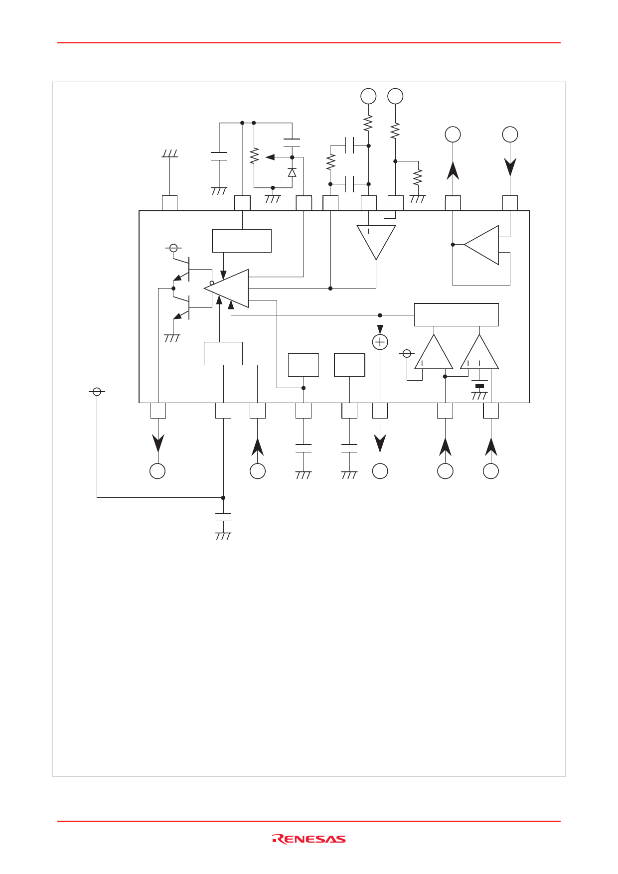
M62501 Application
IN−
IN+
R2
BO
BI
C5
R3
VR1
C3
C2
D1
R1
C4
R4
16
15
14 13
12 11
10
9
VCC
VREF
−
Comp −
+
+
+
−
Latch
UVLO
VREF
GEN
AGC
+
+
VCC
1
2
3
4
5
6
7
8
COSC
CAGC
PWM OUT
TIN
C1
P. OUT
OVP
UVP
C1, C2: Stabilization capacitors of VCC and VREF.
VR1: It is decided considering a load capacity of VREF.
(A load capacity is approximately 5 mA.)
Recommended value is around 10 kΩ.
C3, Dl: They are for the soft start function. A time constant is decided considering VR1.
CAGC: This capacitor is for stabilization of AGC. A larger capacitor improves a stability of the system, however
a system response is degraded.
Recommended value is around 1 µF.
COSC: This capacitor is for a saw wave generation. Recommended value is around 1000 pF.
R1, R2, R3, R4, C4, C5:
They are for a gain setting of the error Amp. R2 should be several kΩ to dozens of kΩ to set a voltage gain
20 dB to 40 dB at f = 1 kHz, so that the feed back loop is stable.
When the voltage gain is too low, it causes jitter.
Recommended values of C4, C5 and R1 are ;
C4 = dozens of pF to several hundreds pF
C5 = several thousands pF to tens of thousands pF
R1 = dozens of kΩ to several hundreds kΩ.
Note: Connect 7-pin and 8-pin terminal to GND when don't use under voltage protection. (UVP)
Rev.2.00 Jun 14, 2006 page 8 of 10
Share Link: 