MAX9513 데이터 시트보기 (PDF) - Maxim Integrated
부품명
상세내역
제조사
MAX9513 Datasheet PDF : 23 Pages
| |||
CVBS Video Filter Amplifier with SmartSleep
and Bidirectional Video Support
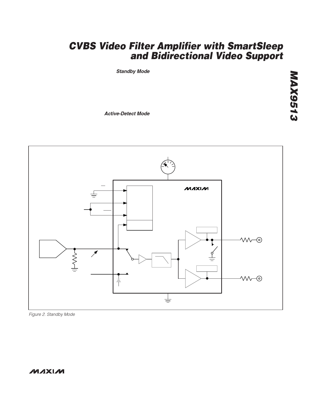
Standby Mode
In standby mode, the filter and output amplifiers are off,
and only the active video detect circuit is operational.
Quiescent current consumption is approximately 7µA
(Figure 2). The active video detect circuit checks
whether sync is present on the CVBSIN signal. If no
sync is detected, the device remains in standby mode.
Active-Detect Mode
The active video detect circuit slices the CVBSIN signal
at 4.7% of the power supply (155mV for a 3.3V supply).
If the transitions occur at a rate of 14.3kHz or higher, a
video signal is present. When the MAX9513 detects a
video signal with sync at the CVBSIN input, the control
logic enters the active-detect mode and enables the
load-sense circuitry (Figure 3). The supply current is
typically 17µA.
If an output load is not connected to any amplifier, the
MAX9513 remains in active-detect mode. Eight times per
second, each load-sense circuit checks for a load by
connecting an internal 15kΩ pullup resistor to the output
for 1ms. If the output is pulled up, no load is present. If
the output stays low, a load is connected.
CURRENT
DAC
+3.3V
INT/EXT
SMARTSLEEP
SHDN
+3.3V
7μA
VDD
CONTROL
LOGIC
ACTIVE VIDEO
DETECT
CVBSIN
BUFFER
NO VIDEO
SIGNAL
LPF
OFF
EXTCVBSIN
OFF
+3.3V
CLAMP
OFF
GND
MAX9513
LOAD SENSE
OFF
6dB
OFF
CVBSOUT1 75Ω
LOAD SENSE
OFF
6dB
OFF
CVBSOUT2 75Ω
CVBS1
CVBS2
Figure 2. Standby Mode
______________________________________________________________________________________ 11
Share Link: 