SMBJ188A 데이터 시트보기 (PDF) - STMicroelectronics
부품명
상세내역
제조사
SMBJ188A Datasheet PDF : 11 Pages
| |||
SMBJ
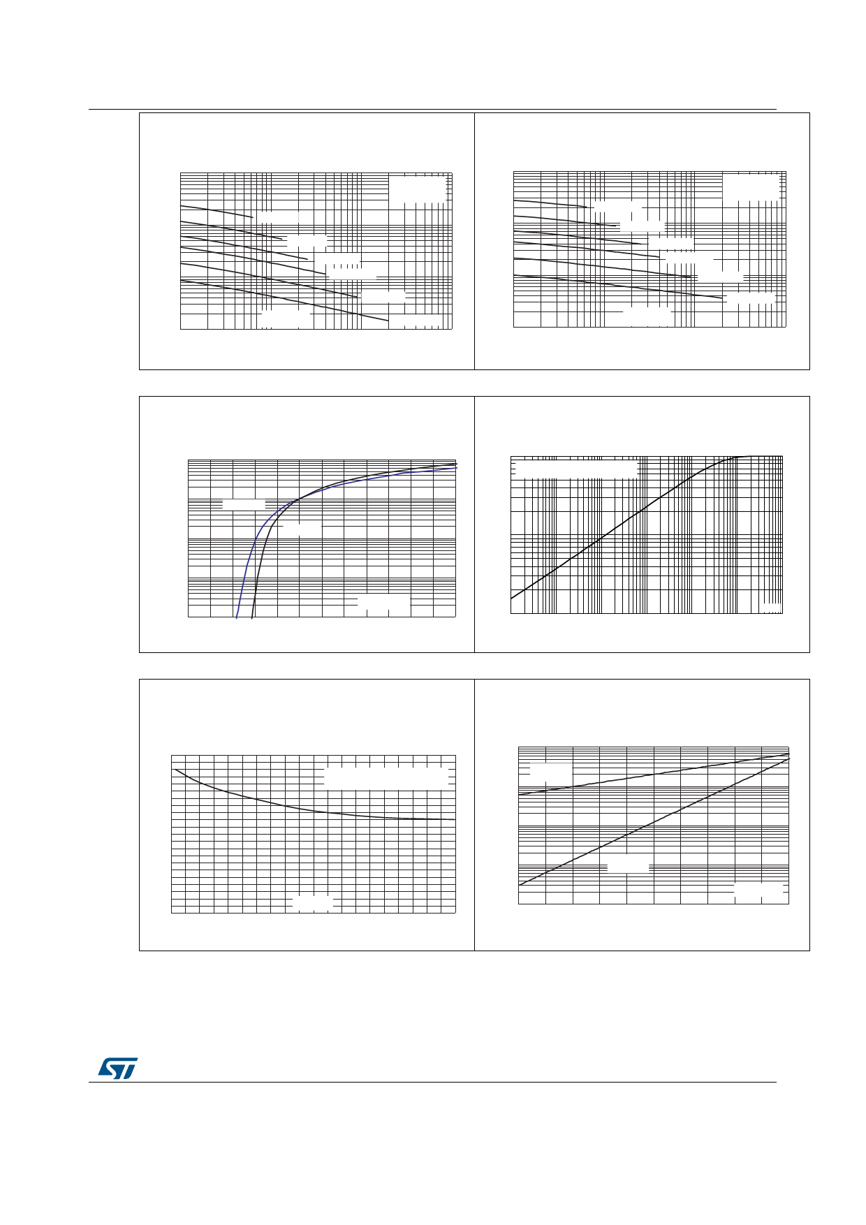
Figure 6: Junction capacitance versus reverse
applied voltage (typical values) (SMBJxxA)
C(pF)
10000
1000
100
10
1
SMBJ5.0A
F=1 MHz
Vosc=30 mVRMS
Tj=25 °C
SMBJ12A
SMBJ24A
SMBJ40A
VR(V)
10
SMBJ85A
SMBJ188A
100
1000
Characteristics
Figure 7: Junction capacitance versus reverse
applied voltage (typical values) (SMBJxxCA)
C(pF)
10000
1000
100
10
1
SMBJ5.0CA
F=1 MHz
Vosc=30 mVRMS
Tj=25 °C
SMBJ12CA
SMBJ24CA
SMBJ40CA
SMBJ85CA
VR(V)
10
SMBJ188CA
100
1000
Figure 8: Peak forward voltage drop versus peak
forward current (typical values)
IFM(A)
1.0E+02
1.0E+01
1.0E+00
Tj =125 °C
Tj =25 °C
Figure 9: Relative variation of thermal impedance
junction to ambient versus pulse duration
1.00
Zth(j-a) / Rth(j-a)
Recommended pad layout
PCB FR4, copper thickness = 35 µm
0.10
1.0E-01
1.0E-02
VFM(V)
0.01
tP(s)
0.0
0.5
1.0
1.5
2.0
2.5
3.0
1.0E-03 1.0E-02 1.0E-01 1.0E+00 1.0E+01 1.0E+02 1.0E+03
Figure 10: Thermal resistance junction to ambient
versus copper surface under each lead (printed
circuit board FR4, eCu = 35 μm)
Rth(j-a)(°C/W)
110
100
(printed ci rc uit boa rd FR4,
90
copper thic knes s = 35 µm)
80
70
60
50
40
30
20
10
SCu(cm²)
0
0.0 0.5 1.0 1.5 2.0 2.5 3.0 3.5 4.0 4.5 5.0
Figure 11: Leakage current versus junction
temperature (typical values)
IR (nA)
1.E+03
1.E+02
VR=VRM
VRM < 10 V
1.E+01
1.E+00
1.E-01
25
VR=VRM
VRM ≥ 10 V
50
75
100
Tj (° C)
125
150
DocID5616 Rev 11
5/11
Share Link: 