TC14433 데이터 시트보기 (PDF) - TelCom Semiconductor Inc => Microchip
부품명
상세내역
제조사
TC14433 Datasheet PDF : 10 Pages
| |||
3-1/2 DIGIT A/D CONVERTERS
TC14433
TC14433A
APPLICATIONS INFORMATION
Figure 10 is an example of a 3-1/2 digit voltmeter using
the TC14433 with common-anode displays. This system
requires a 2.5V reference. Full-scale may be adjusted to
1.999V or 199.9 mV. Input overrange is indicated by flashing
a display. This display uses LEDs with common anode digit
lines. Power supply for this system is shown as a dual ±5V
supply; however, the TC14433 will operate over a wide
voltage range (see recommended operating conditions,
page 2).
The circuit in Figure 11 shows a 3-1/2 digit LCD voltme-
ter. The 14024B provides the low frequency square wave
signal drive to the LCD backplane. Dual power supplies are
shown here; however, one supply may be used when VSS is
connected to VEE. In this case, VAG must be at least 2.8V
above VEE.
When only segments b and c of the decoder are con-
nected to the 1/2 digit of the display, 4, 0, 7 and 3 appear as 1.
The overrange indication (Q3 = 0 and Q0 = 1) occurs
when the count is greater than 1999; e.g., 1.999V for a
reference of 2V. The underrange indication, useful for auto-
ranging circuits, occurs when the count is less than 180; e.g.,
0.180V for a reference of 2V.
CAUTION
If the most significant digit is connected to a
display other than a "1" only, such as a full
digit display, segments other than b and c must
be disconnected. The BCD to 7-segment
decoder must blank on BCD inputs 1010 to 1111.
Figure 14 is an example of a 3-1/2 digit LED voltmeter
with a minimum of external components (only 11 additional
components). In this circuit, the 14511B provides the seg-
ment drive and the 75492 or 1413 provides sink for digit
current. Display is blanked during the overrange condition.
TRUTH TABLE
Coded Condition
BCD to 7-Segment
of MSD
+0
–0
+0 UR
–0 UR
+1
–1
+1 OR
–0 OR
Q3 Q2 Q1 Q0
1 1 10
1 0 10
1 1 11
1 0 11
0 1 00
0 0 00
0 1 11
0 0 11
Decoding
Blank
Blank
Blank
Blank
4–1 Hook up
0–1 only
7–1 segments
3–1 b and c
to MSD
NOTES: Q3 — 1/2 digit, low for "1", high for "0"
Q2 — Polarity: "1" = positive, "0" = negative
Q0 — Out of range condition exists if Q0 = 1. When used in
conjunction with Q3, the type of out of range condition is
indicated; i.e., Q3 = 0 → OR or Q3 = 1 → UR.
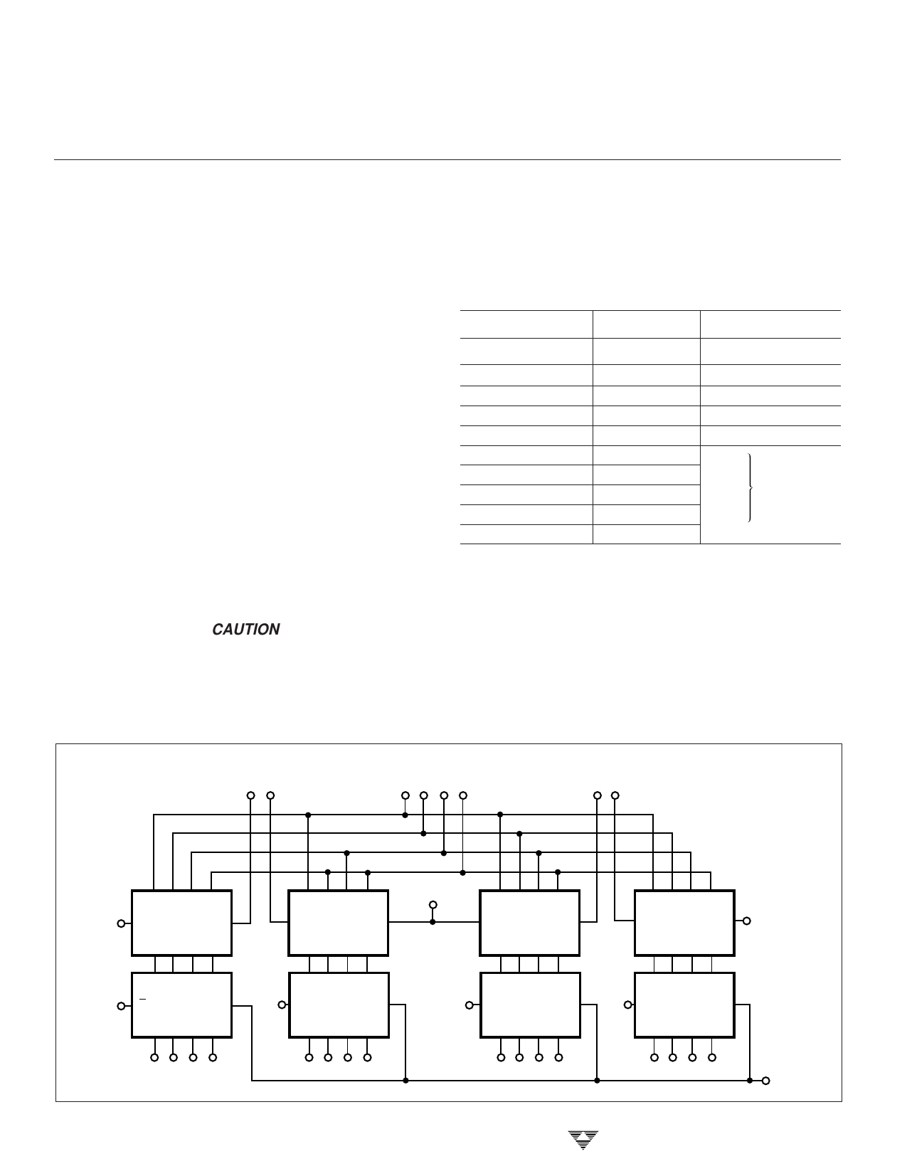
DS1 DS2
MULTIPLEXED
BCD
DS1 DS2
DS3 DS4
D0 D1 D2 D3
VDD POL 14042B C
Q0 Q1 Q2 Q3
D0 D1 D2 D3
VDD R 14175B C
Q0 Q1 Q2 Q3
D0 D1 D2 D3
C 14042B POL
Q0 Q1 Q2 Q3
D0 D1 D2 D3
VDD POL 14175B C
Q0 Q1 Q2 Q3
VDD
D0 D1 D2 D3
POL 14042B C
Q0 Q1 Q2 Q3
D0 D1 D2 D3
C 14042B POL
Q0 Q1 Q2 Q3
VDD
VDD
D0 D1 D2 D3
POL 14175B C
Q0 Q1 Q2 Q3
D0 D1 D2 D3
VDD POL 14175B C
Q0 Q1 Q2 Q3
3-134
EOC
Figure 13. Demultiplexing for TC14433 BCD Data
TELCOM SEMICONDUCTOR, INC.
Share Link: 