TL431AC 데이터 시트보기 (PDF) - Microsemi Corporation
부품명
상세내역
제조사
TL431AC Datasheet PDF : 10 Pages
| |||
TL431
ELECTRICAL CHARACTERISTICS
Tamb = 25°C (unless otherwise specified)
Symbol
Parameter
TL431I
Min. Typ. Max.
TL431AI
Min. Typ. Max.
Vref
∆Vref
∆----V---r--e---f
∆Vka
Iref
∆Iref
Imin
Ioff
ZKA
Reference Input Voltage
VKA = Vref , Ik = 10 mA Tamb = 25°C
Tmin ≤Tamb ≤ Tmax
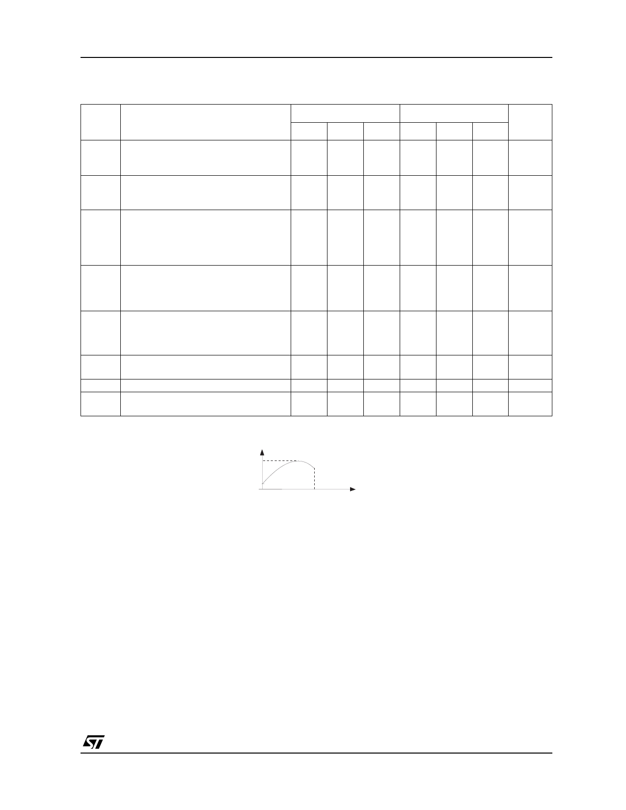
Reference Input Voltage Deviation Over-
Temperature Range - note 1
VKA = Vref , Ik =10 mA,Tmin≤Tamb≤ Tmax
Ratio of Change in Reference Input
Voltage to Change in Cathode to Anode
Voltage
Ik = 10mA
∆VKA = 10V to Vref
∆VKA = 36V to 10V
Reference Input Current
Ik = 10mA, R1 = 10kΩ, R2 = ∞
Tamb = 25°C
Tmin ≤Tamb ≤Tmax
Reference Input Current Deviation
Over Temperature Range
Ik = 10mA, R1 = 10kΩ, R2 =∞
Tmin ≤Tamb ≤ Tmax
Minimum Cathode Current for Regulation
VKA = Vref
Off-State Cathode Current
Dynamic Impedance note 2
VKA = Vref ,∆ Ik = 1 to100mA, f ≤1kHZ
2.44
2.41
2.495 2.55
2.58
7
30
-1.4 -2.7
-1
-2
1.8
4
6.5
0.8
2.5
0.5
1
2.6 1000
0.22 0.5
2.47 2.495 2.52
2.44
2.55
7
30
-1.4 -2.7
-1
-2
1.8
4
6.5
0.8
1.2
0.5
0.7
2.6 1000
0.22 0.5
1∆)V∆reVf r=ef
is defined
Vref max. -
as the difference
Vref min.
between
the
maximum
and
minimum
values
obtained
over
the
full
temperature
range.
Unit
V
mV
mV/V
µA
µA
mA
nA
Ω
V ref max.
V ref min.
T1
2)
The
dynamic
Impedance
is
definied
as
ZKA =
∆----V-----K-----A--
∆IK
T2
Temperature
3/10
Share Link: 