P1553ACMC 데이터 시트보기 (PDF) - Littelfuse, Inc
부품명
상세내역
제조사
P1553ACMC Datasheet PDF : 4 Pages
| |||
SIDACtor® Protection Thyristors
Broadband Optimized™ Protection
Capacitance Values
Part Number
P1553ACMCLxx
P1803ACMCLxx
P2103ACMCLxx
P2353ACMCLxx
P2703ACMCLxx
P3203ACMCLxx
P3403ACMCLxx
P5103ACMCLxx
pF
Pin 1-2 / 3-2
Tip-Ground, Ring-Ground
MIN
MAX
30
55
30
60
30
45
25
45
25
40
25
40
20
35
20
30
pF
Pin 1-3
Tip-Ring
MIN
MAX
20
35
15
30
15
30
15
30
15
30
15
30
15
25
10
20
Note: Off-state capacitance (C ) is measured at 1 MHz with a 2 V bias.
O
Surge Ratings
0.2x310 1
0.5x700 2
2x10 1
2x10 2
8x20 1
1.2x50 2
10x160 1
10x160 2
IPP
10x560 1
10x560 2
A min
A min
A min
A min
A min
C
50
500
400
200
150
Notes:
1 Current waveform in μs
2 Voltage waveform in μs
- Peak pulse current rating (IPP) is repetitive and guaranteed for the life of the product.
- IPP ratings applicable over temperature range of -40ºC to +85ºC
- The device must initially be in thermal equilibrium with -40°C < T < +150°C
J
5x320 1
9x720 2
A min
200
10x360 1
10x360 2
A min
175
10x1000 1
10x1000 2
A min
100
5x310 1
10x700 2
A min
200
ITSM
50/60 Hz
di/dt
A min A/μs max
30
500
Thermal Considerations
Package
Modified
TO-220
PIN 1
PIN 3
PIN 2
Symbol
Parameter
T
Operating Junction Temperature Range
J
TS
Storage Temperature Range
R
0JA
Thermal Resistance: Junction to Ambient
Value
-40 to +150
-65 to +150
50
Unit
°C
°C
°C/ W
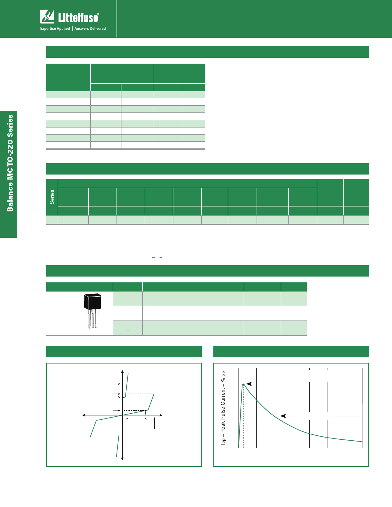
V-I Characteristics
+I
IT
IS
IH
IDRM
-V
+V
VT
VDRM
VS
-I
86
tr x td Pulse Waveform
tr = rise time to peak value
100
Peak td = decay time to half value
Value
Waveform = tr x td
50
Half Value
0
0 tr
td
t – Time (μs)
© 2010 Littelfuse, Inc.
Specifications are subject to change without notice.
Please refer to www.littelfuse.com for current information.
Share Link: 