SFH6345 데이터 시트보기 (PDF) - Infineon Technologies
부품명
상세내역
제조사
SFH6345 Datasheet PDF : 4 Pages
| |||
Characteristics (TA=0° to 70°C, unless otherwise specified, typical values TA=25°C)
Description
Symbol Min. Typ. Max. Unit
Emitter (IR GaAlAs)
Forward Voltage
VF
—
1.6
1.9
V
Reverse Current
IR
—
0.5
10
µA
Capacitance
C0
—
75
—
pF
Thermal Resistance
R thJA
—
700
—
K/W
Detector (Si Photodiode + Transistor)
Supply Current, Logic High
ICCH
—
0.01 1
µA
—
2
Output Current, Output High
IOH
—
.003 0.5
µA
—
.01
1
—
—
—
50
—
Capacitance
Thermal Resistance
Package
C CE
—
3
—
pF
RthJA
—
300
—
K/W
Coupling Capacitance
Coupling Transfer Ratio
CC
—
0.6
—
pF
IC/IF
19
30
—
%
15
—
—
—
Collector Emitter Saturation Voltage VOL
Supply Current, Logic Low
ICCL
—
0.1
0.4
V
—
80
200
µA
Condition
IF=16 mA
VR=3 V
VR=0 V, f=1 MHz
—
IF=0, VO (open), VCC=15 V, TA=25°C
IF=0, VO (open), VCC=15 V
IF=0, VO=VCC=5.5 V, TA=25°C
IF=0, VO=VCC=15 V, TA=25°C
IF=0, VO=VCC=15 V
VCE=5 V, f=1 MHz
—
—
IF=16 mA, VO=0.4 V, VCC=4.5 V, TA=25°C
IF=16 mA, VO=0.5 V, VCC=4.5 V
IF=16 mA, IO=2.4 mA, VCC=4.5 V, TA=25°C
IF=16 mA, VO open, VCC=15 V
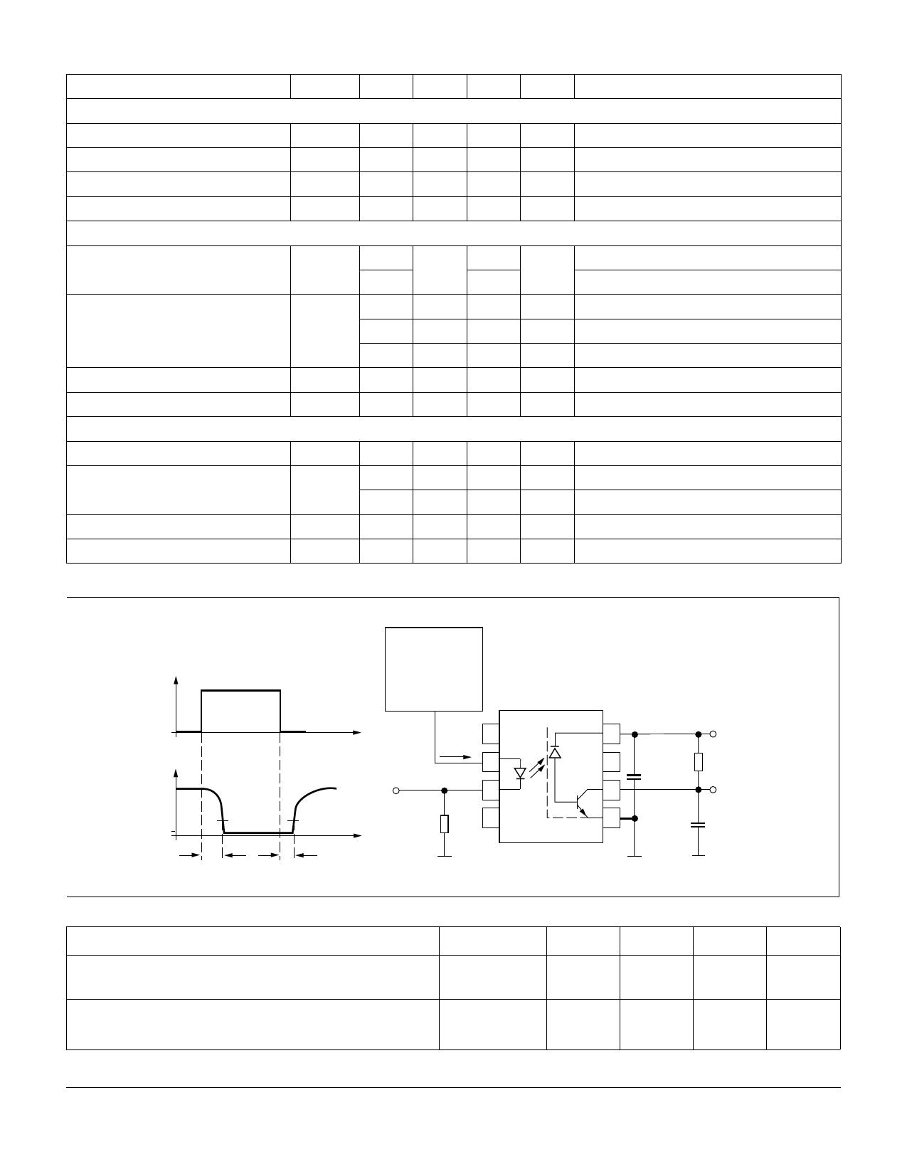
Figure 1. Switching times (typ.)
IF
VO
VOL
tPHL
t
5V
1.5 V
t
tPLH
Pulse generator
ZO=50 Ω
tr,tf=5 ns
duty cycle 10%
t≤100 µs
1
IF
2
IF Monitor
3
100 Ω 4
8
5V
7
C=100 nF RL
6
VO
5
CL=15 pF
Description
Propagation Delay Time (High–Low) IF=16 mA, VCC=5 V,
RL=1.9 kΩ, TA=25°C
Propagation Delay Time (Low–High) IF=16 mA, VCC=5 V,
RL=1.9 kΩ, TA=25°C
Symbol
tPHL
tPLH
2000 Infineon Technologies Corp. • Optoelectronics Division • San Jose, CA
www.infineon.com/opto • 1-888-Infineon (1-888-463-4636)
OSRAM Opto Semiconductors GmbH & Co. OHG • Regensburg, Germany
www.osram-os.com • +49-941-202-7178
2
Min.
—
—
Typ.
0.3
0.3
Max.
Unit
0.8
µs
0.8
µs
SFH6345
May 17, 2000–09
Share Link: 