AD829SE/883B 데이터 시트보기 (PDF) - Analog Devices
부품명
상세내역
제조사
AD829SE/883B Datasheet PDF : 16 Pages
| |||
AD829
Table I. Component Selection for Shunt Compensation
Follower
Gain
1
2
5
10
20
25
100
Inverter
Gain
–1
–4
–9
–19
–24
–99
R1
(⍀)
Open
1k
511
226
105
105
20
R2
(⍀)
100
1k
2.0 k
2.05 k
2k
2.49
2k
CL
(pF)
0
5
1
0
0
0
0
CCOMP
(pF)
68
25
7
3
0
0
0
Slew
Rate
(V/s)
16
38
90
130
230
230
230
–3 dB Small Signal
Bandwidth (MHz)
66
71
76
65
55
39
7.5
Table I gives the recommended CCOMP and CLEAD values, as
well as the corresponding slew rates and bandwidth. The capacitor
values were selected to provide a small signal frequency response
with less than 1 dB of peaking and less than 10% overshoot. For
this table, supply voltages of ± 15 V should be used. Figure 9 is
a graphical extension of the table that shows the slew rate/gain
trade-off for lower closed-loop gains, when using the shunt
compensation scheme.
100
1k
CCOMP
10
SLEW RATE
100
VS = ؎15V
1
10
1
10
100
NOISE GAIN
Figure 9. Value of CCOMP and Slew Rate vs. Noise Gain
Current Feedback Compensation
Bipolar, nondegenerated, single pole, and internally compensated
amplifiers have their bandwidths defined as
fT
=
2
π
re
1
CCOMP
=
2
π
kT
q
I
CCOMP
where
fT is the unity gain bandwidth of the amplifier.
I is the collector current of the input transistor.
CCOMP is the compensation capacitance.
re is the inverse of the transconductance of the input transistors.
kT/q approximately equals 26 mV @ 27°C.
Since both fT and slew rate are functions of the same variables,
the dynamic behavior of an amplifier is limited. Since
Slew Rate = 2I
CCOMP
then
Slew Rate
fT
=
4
π
kT
q
This shows that the slew rate will be only 0.314 V/µs for every
MHz of bandwidth. The only way to increase slew rate is to
increase the fT, and that is difficult because of process limitations.
Unfortunately, an amplifier with a bandwidth of 10 MHz can
only slew at 3.1 V/µs, which is barely enough to provide a full
power bandwidth of 50 kHz.
The AD829 is especially suited to a new form of compensation
that allows for the enhancement of both the full power band-
width and slew rate of the amplifier. The voltage gain from the
inverting input pin to the compensation pin is large; therefore, if
a capacitance is inserted between these pins, the amplifier’s
bandwidth becomes a function of its feedback resistor and the
capacitance. The slew rate of the amplifier is now a function of
its internal bias (2I) and the compensation capacitance.
Since the closed-loop bandwidth is a function of RF and CCOMP
(Figure 10), it is independent of the amplifier closed-loop gain,
as shown in Figure 12. To preserve stability, the time constant
of RF and CCOMP needs to provide a bandwidth of less than
65 MHz. For example, with CCOMP = 15 pF and RF = 1 kΩ, the
small signal bandwidth of the AD829 is 10 MHz. Figure 11 shows
that the slew rate is in excess of 60 V/µs. As shown in Figure 12,
the closed-loop bandwidth is constant for gains of –1 to –4; this is
a property of current feedback amplifiers.
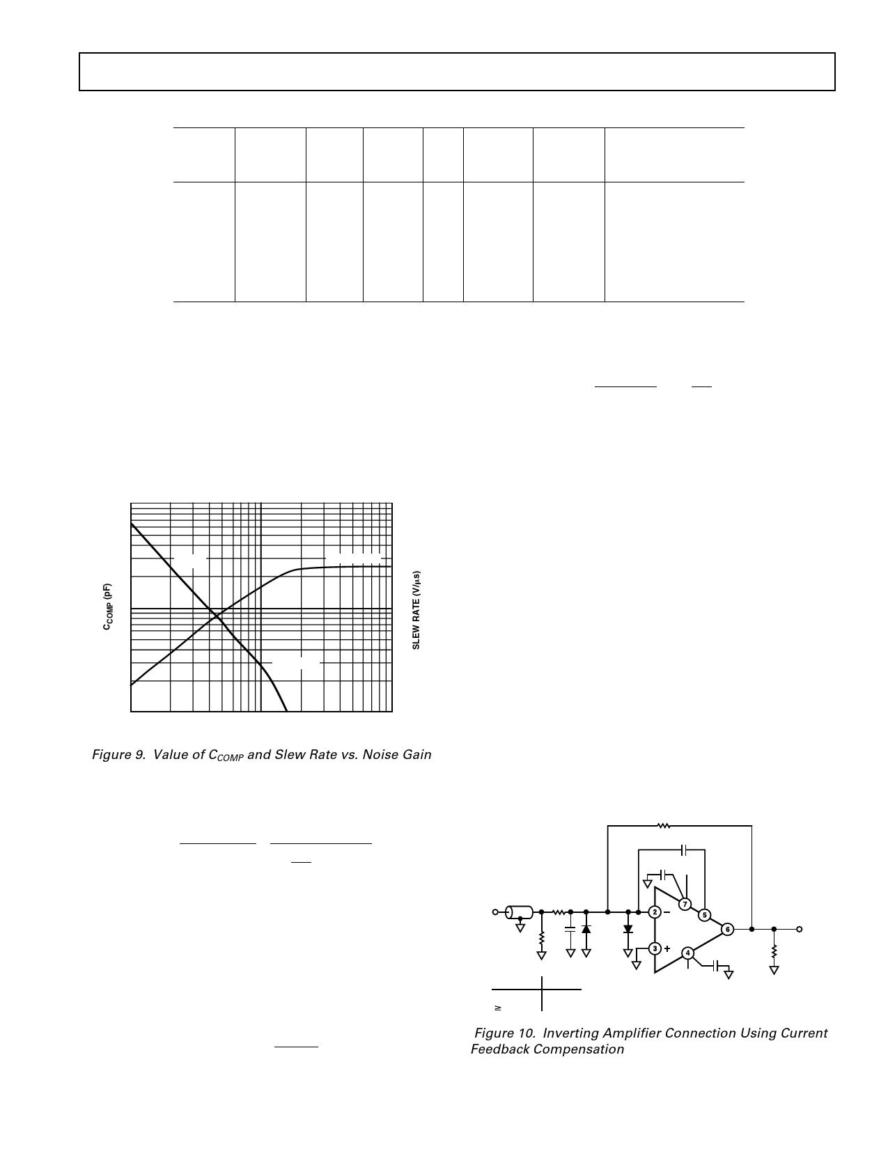
RF
CCOMP
50⍀
COAX
CABLE
VIN
R1
C1*
50⍀
IN4148
0.1F +VS
AD829
0.1F
*RECOMMENDED VALUE
OF CCOMP FOR C1
–VS
<7pF
7pF
0pF
15pF
CCOMP SHOULD NEVER EXCEED
15pF FOR THIS CONNECTION
VOUT
RL
1k⍀
Figure 10. Inverting Amplifier Connection Using Current
Feedback Compensation
REV. G
–11–
Share Link: 