STPS2H100(2010) 데이터 시트보기 (PDF) - STMicroelectronics
부품명
상세내역
제조사
STPS2H100 Datasheet PDF : 10 Pages
| |||
STPS2H100
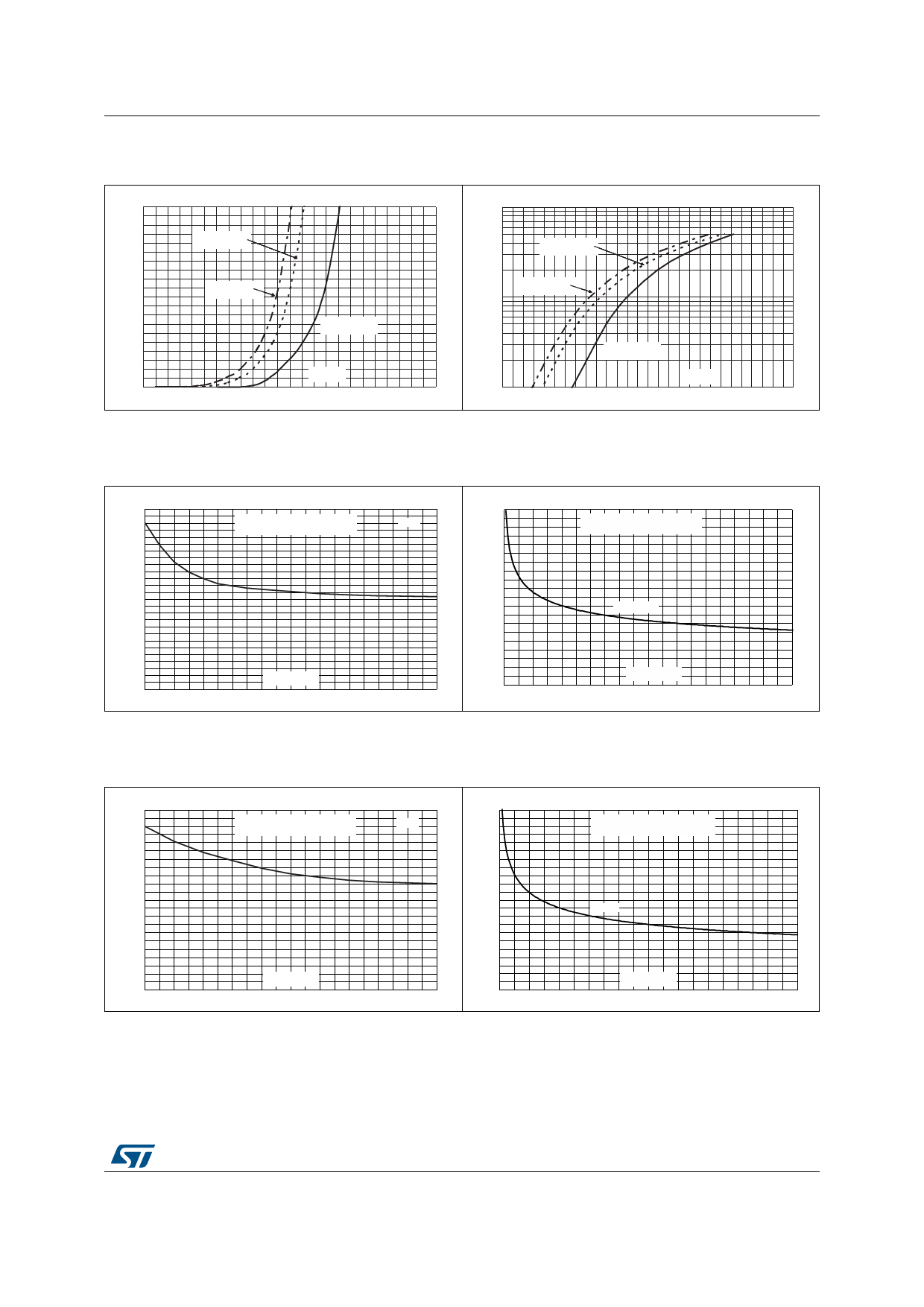
Characteristics
Figure 13. Forward voltage drop versus
forward current (low level)
2.0 IFM(A)
1.8
1.6
Tj=125°C
(Maximum values)
1.4
1.2
Tj=125°C
1.0
(Typical values)
0.8
Tj=25°C
0.6
(Maximum values)
0.4
0.2
VFM(V)
0.0
0.0 0.1 0.2 0.3 0.4 0.5 0.6 0.7 0.8 0.9 1.0 1.1 1.2
Figure 14. Forward voltage drop versus
forward current (high level)
100 IFM(A)
Tj=125°C
(Maximum values)
Tj=125°C
(Typical values)
10
Tj=25°C
(Maximum values)
VFM(V)
1
0.4 0.5 0.6 0.7 0.8 0.9 1.0 1.1 1.2 1.3 1.4 1.5 1.6 1.7 1.8
Figure 15. Thermal resistance junction to
ambient versus copper surface
under each lead (SMA)
Rth(j-a)(°C/W)
130
120
110
Epoxy printed circuit board FR4,
Copper thickness = 35 µm
100
90
80
70
60
50
40
30
20
10
SCU(cm²)
0
0.0 0.5 1.0 1.5 2.0 2.5 3.0 3.5 4.0
SMA
4.5 5.0
Figure 16. Thermal resistance junction to
ambient versus copper surface
under each lead (SMB)
Rth(j-a)(°C/W)
110
100
Epoxy printed circuit board FR4,
SMB
Copper thickness = 35 µm
90
80
70
60
50
40
30
20
10
SCU(cm²)
0
0.0 0.5 1.0 1.5 2.0 2.5 3.0 3.5 4.0 4.5 5.0
Figure 17.
Thermal resistance junction to ambient versus copper surface under each lead
(SMB flat)
Rth(j-a)(°C/W)
110
100
90
Epoxy printed circuit board FR4,
Copper thickness = 35 µm
80
70
60
50
SMB flat
40
30
20
10
SCU(cm²)
0
0.0 0.5 1.0 1.5 2.0 2.5 3.0 3.5 4.0 4.5 5.0
Doc ID 6115 Rev 7
5/10
Share Link: 