LV4904V-TLM-E 데이터 시트보기 (PDF) - ON Semiconductor
부품명
상세내역
제조사
LV4904V-TLM-E Datasheet PDF : 25 Pages
| |||
LV4904V
1. Mode Switching (combined I2C bus and pin setting mode pin setting mode)
1.1 Description of modes
Combined I2C bus and pin setting mode
In this mode, the function settings can be established according to both the I2C bus and pins. With some pin
settings, the settings established according to the I2C bus registers are enabled; with the other pin settings, the
settings established according to the pins are enabled.
Pin setting mode
In this mode, the LV4904V is controlled only by pin settings. This has the advantage of not requiring the I2C bus
for control purposes, but the parameters that can be set are limited. Table 1.1 below lists the differences between
the items that can be set through the I2C bus and those that can be set using only the pins.
Symbol
DFORM
MCKFS
SRATE
GAIN
MUTE
PSTP
IDPEN
MDIDX
NSORD
Table 1.1 Differences between combined I2C bus and pin setting mode
Description
Settings Using the I2C Bus
Settings Using the Pin
Input data format
7 formats available
2 formats available
Master clock (MCK) rate
4 rates available (256fs, 384fs, 512fs, and 768fs)
2 rates available (256fs and 512fs)
Input data sampling rate
32 kHz to 192 kHz
44.1 kHz to 96 kHz
Gain controller setting
Muting
PWM output stop setting
50% pulse setting during mute
Modulation index setting
Noise shaping orders
2-channel independently controllable
2-channel independently controllable
2-channel independently controllable
ON or OFF setting enabled
87.5% 100% switchable
Fifth order seventh order switchable
2-channel common control
2-channel common control
2-channel common control
ON fixed
87.5% fixed
Seventh order fixed
1.2 Mode setting methods
Combined I2C bus and pin setting mode
The combined I2C bus and pin setting mode is established when RSTB is set from low to high in a state other than
SCL=SDA=low. However, for this to happen, it is necessary that proper clocks have been input from the MCK
pin.
SCL
SDA
RSTB
Combined I2C bus and pin setting mode
Figure1-1 Placing the IC in combined I2C bus and pin setting mode
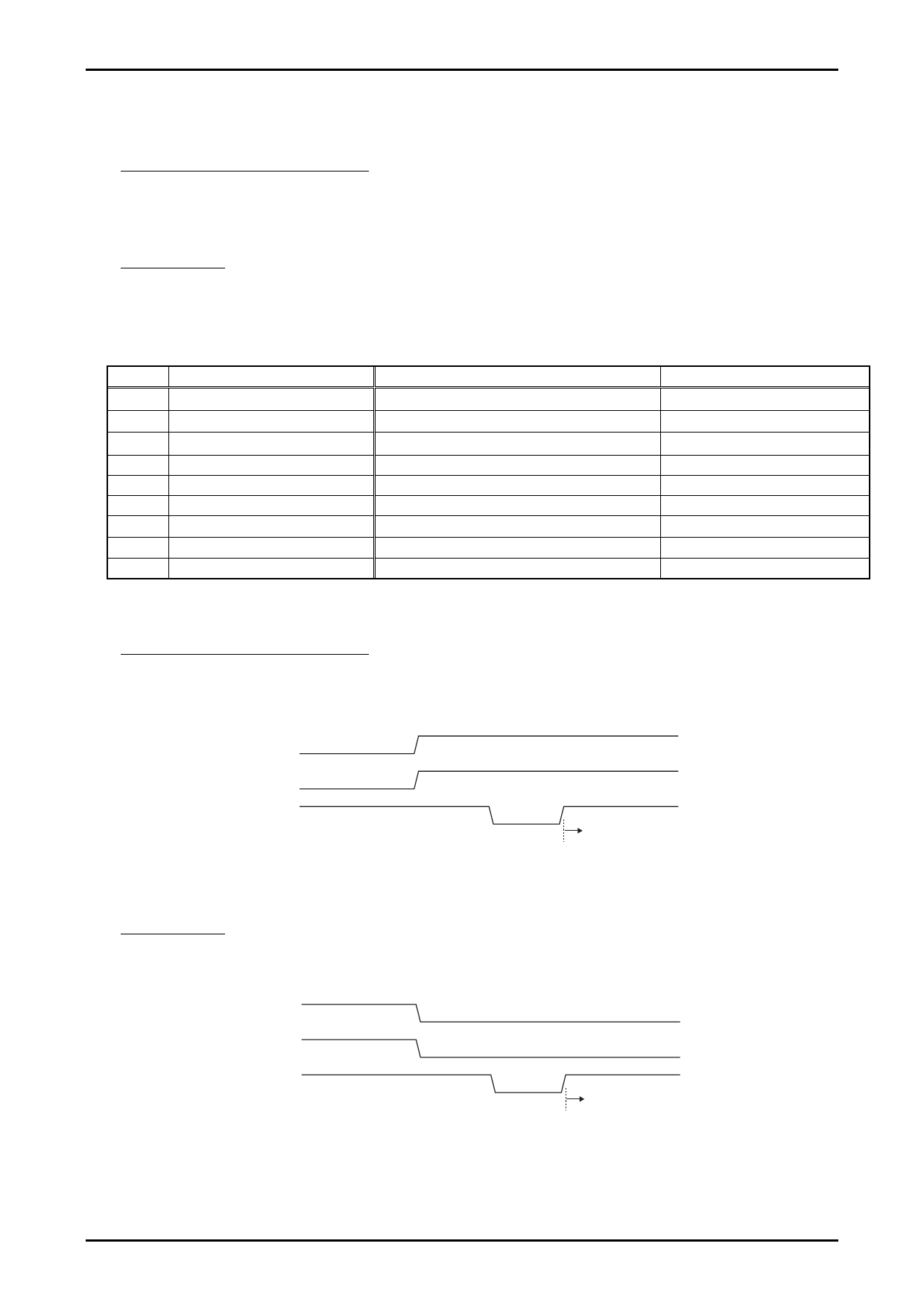
Pin setting mode
The pin setting mode is established when RSTB is set from low to high in the SCL=SDA=low state. However, for
this to happen, it is necessary that proper clocks have been input from the MCK pin.
SCL
SDA
RSTB
Pin setting mode
Figure1-2 Placing the IC in pin setting mode
No.A1963-8/25
Share Link: 