MB1505W-F 데이터 시트보기 (PDF) - Diodes Incorporated.
부품명
상세내역
제조사
MB1505W-F Datasheet PDF : 4 Pages
| |||
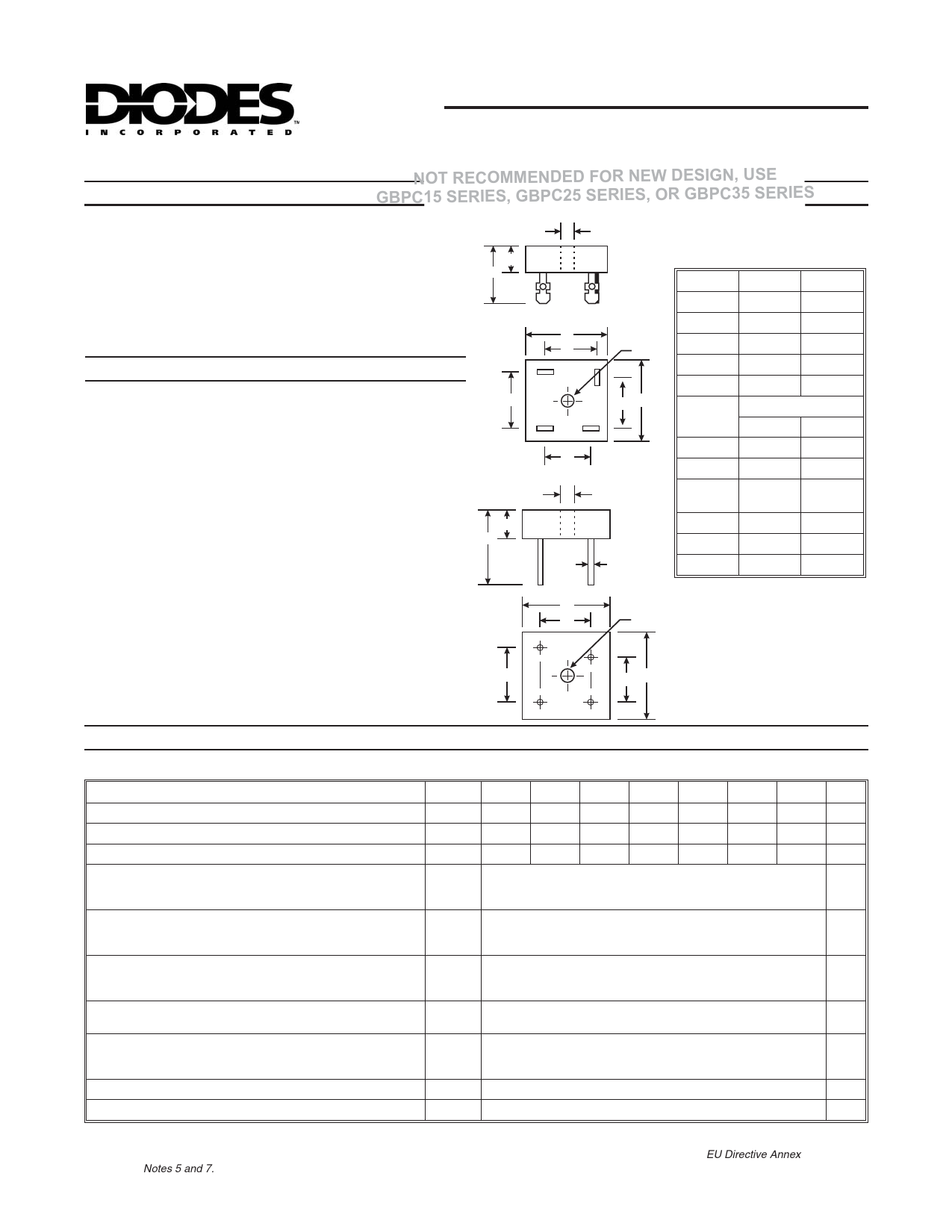
MB15(W) / 25(W) / 35(W)
HIGH CURRENT SILICON BRIDGE RECTIFIER
Features
NOT RECOMMENDED FOR NEW DESIGN, USE
GBPC15 SERIES, GBPC25 SERIES, OR GBPC35 SERIES
· High Conductivity
MB
H
· Metal Case
· Superior Thermal Design
B
· Terminals Solderable per MIL-STD-202, Method 208
E
Dim
Min
Max
· Universal Terminals; Snap-on, Solder or P.C. Board Mounting
A
28.40 28.70
· Lead Free Finish, RoHS Compliant (Date Code 0514+)
(Note 2)
B
10.97 11.23
A
C
H
C
15.50 17.60
Mechanical Data
· Terminals: 0.25" Faston Terminals
· Case material - UL Flammability Rating Classification 94V-0
· Moisture sensitivity: Level 1 per J-STD-020C
· Approx Weight: 29 grams
· Mounting Position: Bolt Down on Heat-sink with Silicone
Thermal Compound Between Bridge and Mounting Surface for
Maximum Heat Transfer Efficiency
(AC)
J
(-)
(+)
(AC)
CA
G
MB-W
H
E
22.86 25.40
G
13.30 15.30
H
Hole for #10 screw
4.85Æ 5.59Æ
J
17.10 19.10
K
10.40 12.40
L
0.97Æ
Nominal
1.07Æ
· Mounting Torque: 20 in. lb. Max.
N
M
30.50
¾
· Polarity: Polarity Symbols Marked on Case
M
N
10.97 11.23
L
P
17.10 19.10
(AC)
P
A
P
H
(+)
KA
(-)
(AC)
Maximum Ratings and Electrical Characteristics
Rating at 25°C ambient temperature unless otherwise specified.
Suffix “W” denotes wire leads
Characteristic
Symbol -05
-1
-2
-4
-6
-8
-10 Units
Maximum Recurrent Peak Reverse Voltage
VRRM
50
100 200 400 600 800 1000 V
Maximum RMS Voltage
VRMS
35
70
140 280 420 560 700 V
Maximum DC Blocking Voltage
VDC
50
100 200 400 600 800 1000 V
Maximum Average
MB15
15.0
Rectified Output Current
@ TC = 55°C
MB25
MB35
I(AV)
25.0
35.0
A
Peak Forward Surge Current Single
MB15
300
Half Sine-Wave Superimposed on
Rated Load
MB25
MB35
IFSM
300
400
A
Maximum Instantaneous @ 7.5A
Forward Voltage Drop per @12.5A
Rated Load @17.5A
MB15
MB25
MB35
VF
1.1
1.1
V
1.2
Maximum Reverse DC current at Rated
DC Blocking Voltage (per Element)
I2t rating for fusing (8.3ms)
@TA = 25°C
@TA = 100°C
IR
MB15
MB25
MB35
I2t
10
µA
1.0
mA
373
373
A2s
664
Typical Thermal Resistance (Note 1)
RqJC
2.5
°C/W
Operating and Storage Temperature Range
TJ, TSTG
-55 to +150
°C
Notes: 1. Thermal Resistance from junction to case
2. EC Directive 2002/95/EC (RoHS) revision 13.2.2003. Glass and High Temperature Solder Exemptions Applied, see EU Directive Annex
Notes 5 and 7.
DS21303 Rev. 7 - 3
1 of 4
MB15(W)/25(W)/35(W)
www.diodes.com
ã Diodes Incorporated
Share Link: 