NTE5705 데이터 시트보기 (PDF) - NTE Electronics
부품명
상세내역
제조사
NTE5705 Datasheet PDF : 4 Pages
| |||
Electrical Characteristics (Cont’d):
Parameter
Symbol
Test Conditions
Triggering (Cont’d)
Maximum Gate Current Required IGT TJ = --40°C
to Trigger
TJ = +25°C
Anode Supply = 6V
Resistive Load
TJ = +125°C
Maximum Gate Voltage that will
not Trigger
VGD
TJ = +125°C, Rated VDRM Applied
Blocking
Maximum Critical Rate of Rise of
Off--State Voltage
Maximum Peak Reverse and
Off--State Leakage Current
at VRRM, VDRM
RMS Isolation Voltage
dv/dt
IRM
IDM
VINS
TJ = +125°C, Exponential to 0.67VDRM,
Gate Open Circuit
TJ = TJ Max, Gate Open Circuit
50Hz, Circuit to Base, All Terminals Shorted
Rating Unit
90 mA
60 mA
35 mA
0.2 V
200 V/ms
10 mA
2.0 mA
2500 V
Note 2. I2t for time tx = I2 Öt ¯ Ötx.
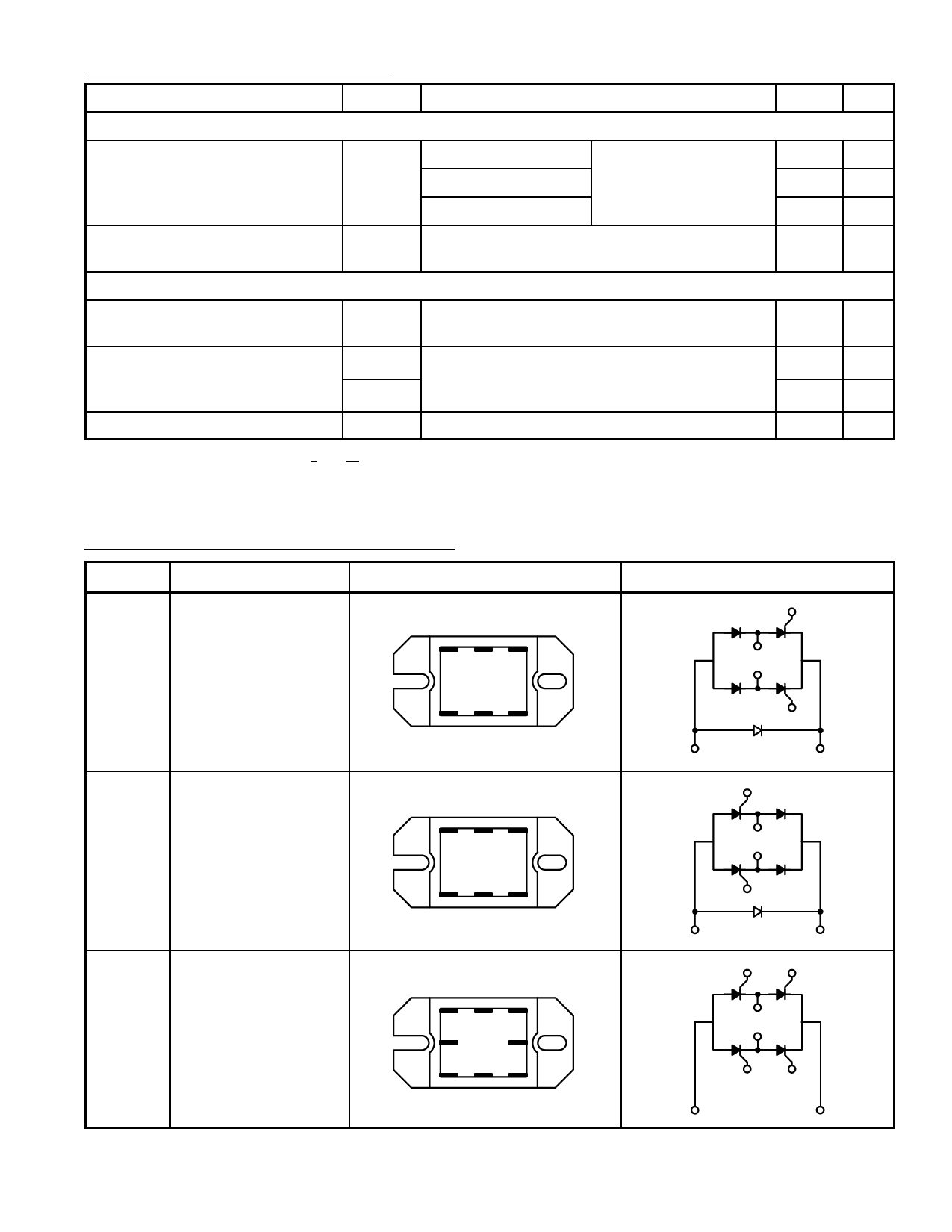
Pin Connection and Schematic Diagrams:
NTE No.
Description
Terminal Positions
5700
Single Phase,
Hybrid Bridge,
Common Cathode,
Freewheeling Diode
AC1 G1 (- )
AC2 G2 (+)
Schematic Diagrams
G1
AC1
*
AC2
G2
5701
Single Phase,
Hybrid Bridge,
Common Anode,
Freewheeling Diode
AC1 G1 (- )
AC2 G2 (+)
(- )
(+)
G1
AC1
*
AC2
G2
5702
Single Phase,
All SCR Bridge
AC2 G2 (- )
G1 G4
AC1 G3 (+)
(- )
(+)
G3
G1
AC1
*
AC2
G4
G2
(- )
(+)
* For transient protection, a Metal Oxide Varistor (MOV) may be connected externally across terminals AC1 & AC2.
Share Link: 