NTE1888 데이터 시트보기 (PDF) - NTE Electronics
부품명
상세내역
제조사
NTE1888 Datasheet PDF : 4 Pages
| |||
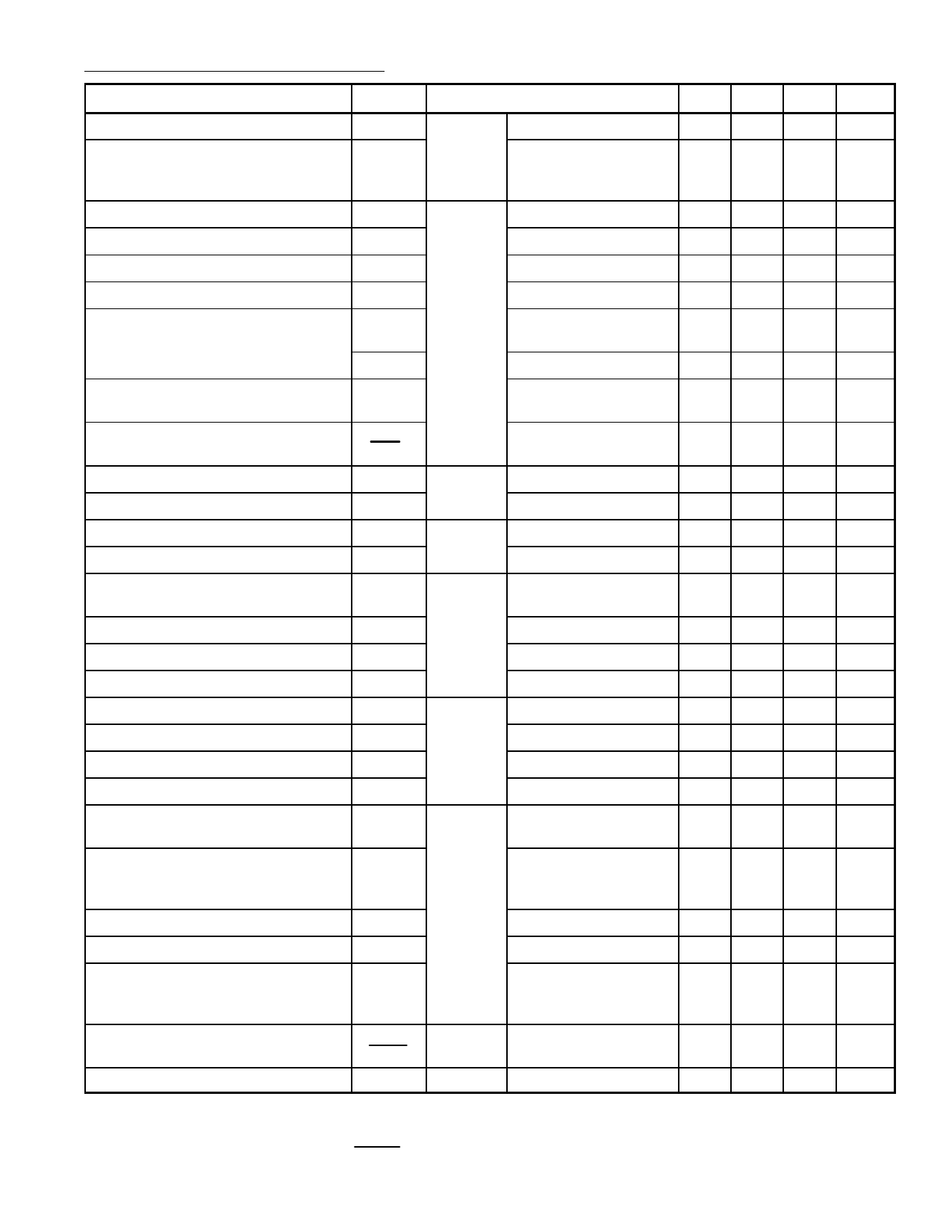
Electrical Characteristics (Cont’d): (TA = +25°C unless otherwise specified)
Parameter
Symbol
Test Conditions
Min Typ Max Unit
Reference Voltage
Minimum Width of Frame Pulse
(when synchronized with TTL
signal)
V15
MWF
@ Pin15 I15 = –1µA
1.4 1.75 2.0 V
50 –
–
µs
Low Threshold Voltage
High Threshold Voltage
Bias Current
Discharge Impedance
Free Running Line Period
LT9
HT9
BI9
DR9
FLP1
@ Pin9
R = 34.9kΩ to Vcc1,
C = 2.2nF to GND
2.8 3.2 3.6 V
6.4 6.6 7.8 V
– 100 –
nA
1.0 1.4 1.8 kΩ
62 64 66 µs
FLP2
R = 13.7kΩ, C = 2.2nF –
27
–
µs
Oscilator Threshold for Line Output
OT9
Pulse Triggering
– 4.6 –
V
Horizontal Frequency Drift
DF
w/Temperature
∆Θ
–
2
– Hz/°C
Saturation Voltage
Output Pulse Width
LV14
OPW
@ Pin14 I14 = 200mA
Line Period = 64µs
– 1.1 1.6 V
20 22 24 µs
Bias Voltage
Input Impedance
Output Current During Synchro
Pulse
V11
@ Pin11
Z11
I10
@ Pin10
1.8 2.4 3.2 V
4.5 5.8 8.0 kΩ
250 450 800 µA
Current Ratio
Leakage Current
Control Range Voltage
Low Threshold Voltage
High Threshold Voltage
Bias Current
Discharge Impedance
Free Running Frame Period
Minimum Frame Period
RI10
LI10
CV10
LT1
HT1
BI1
DR1
FFP1
MFP
Positive/Negative
@ Pin1
@ Pin1
R = 845kΩ to Vcc1,
C = 180nF to GND
I15 = –100µA,
R = 845kΩ to Vcc1,
C = 180nF to GND
0.95 1.0 1.05
–2
–
+2
µA
2.6 – 7.1 V
1.6 2.0 2.3 V
2.6 3.1 3.6 V
–
30
–
nA
300 470 700 W
20.5 23.0 25.0 ms
– 12.8 –
ms
Free Running Frame Period
FFP2
R = 408kΩ, C = 220nF – 14.3 –
ms
Frame Period Ratio
FPR
Note 1
1.7 1.8 1.9
Frame Sawtooth Gain
Vertical Frequency Drift
w/Temperature
Operating Voltage
FG
Between Pin1 and
– –0.4 –
Non–Inverting input of
the Frame Amplifier
DF
@ Pin1
∆Θ
– 4.1–3 – Hz/°C
V7
@ Pin7 w/Flyback Generator
10
–
58
V
Note 1. Frame Period Ratio = FFP
MFP
Share Link: 