NTE7133 데이터 시트보기 (PDF) - NTE Electronics
부품명
상세내역
제조사
NTE7133 Datasheet PDF : 7 Pages
| |||
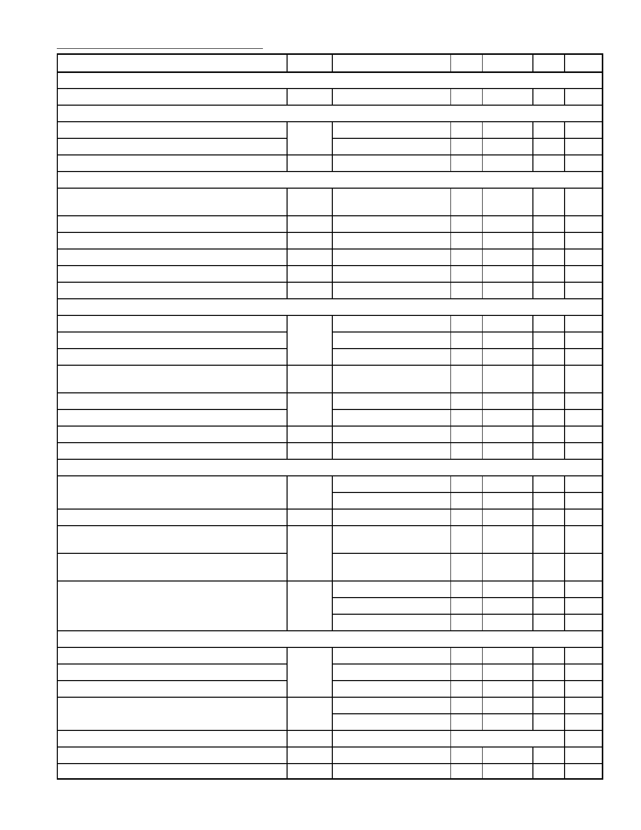
Electrical Characteristics (Cont’d): (VP = 12V, TA = +25°C unless otherwise specified)
Parameter
Symbol Test Conditions
Min Typ Max Unit
VGA/Autosync Mode Switch
Input Voltage LOW to Force Autosync Mode
V7
Horizontal Comparator PLL1
Upper Control Voltage Limitation
V17
Lower Control Voltage Limitation
0
–
50 mV
–
5.9
–
V
–
5.1
–
V
Control Current
I17
Horizontal Oscillator
– ±0.083I18 –
µA
Center Frequency
Deviation of Center Frequency
Temperature Coefficient
fOSC
∆fOSC
TC
R18 = 2.4kΩ (Pin18),
C19 = 10nF (Pin19)
– 31.45 – kHz
–
–
±3.0 %
–
+200 +300 10–6/K
Relative Holding/Catching Range
External Oscillator Current
Voltage at Reference Current Input (Pin18)
Horizontal PLL2
Upper Clamping Level of Flyback Input
Lower Clamping Level of Flyback Input
H–Flyback Slicing Level
ϕH/tH
I18
V18
V2 I2 = 6mA
I2 = –1mA
±6.0 ±6.5 ±7.3 %
–0.5
–
–4.3 mA
2.35 2.5 2.65 V
–
5.5
–
V
– –0.75 –
V
–
3.0
–
V
Delay Between Middle of Sync and Middle of
td/tH
H–Flyback Related to tH
Upper Control Voltage Limitation
V20
Lower Control Voltage Limitation
–
3.0
–
%
–
6.2
–
V
–
4.8
–
V
Control Current
I20
PLL2 Control range Related to tH
∆t/tH
Horizontal Output (Open–Collector)
– ±0.083I18 –
µA
30
–
–
%
Output Voltage LOW
V3 I3 = 20mA
–
–
0.3 V
I3 = 60mA
–
–
0.8 V
tH Duty Cycle
tp/tH
42
45
48 %
Threshold to Activate Too Low Supply Voltage
VP Horizontal Output OFF –
5.6
–
V
Protection
Threshold to Activate Too Low Supply Voltage
Protection
Horizontal Output ON
–
5.8
–
V
Jitter of Horizontal Output
∆tH f = 31kHz
f = 64kHz
–
–
3.5 ns
–
–
1.9 ns
f = 100kHz
–
–
1.2 ns
Horizontal Clamping/Blanking Generator Output
Output Voltage LOW
Blanking Output Voltage
V8
Internal V Blanking
–
–
0.9 V
1.6
1.9
2.2 V
Clamping Output Voltage
H–Sync on Pin9
5.15 5.4 5.65 V
Internal Sink Current for All Output Levels
I8 H and V Scanning
2.3
External Load Current –
2.9
3.5 mA
–
–3.0 mA
Clamping Pulse Start
t8
Clamping Pulse Width
tclp
Steepness of Rise and Fall Times
S
With End of H–Sync
0.8
1.0
1.2 µs
–
60
75 ns/V
Share Link: 