NTE7159 데이터 시트보기 (PDF) - NTE Electronics
부품명
상세내역
제조사
NTE7159 Datasheet PDF : 3 Pages
| |||
Electrical Characteristics (Cont’d): (TA = +25°C, VCC = 12V unless otherwise specified)
Parameter
Symbol
Test Conditions
Min Typ Max Unit
Current Limitation Section
First Current Limitation Threshold
Second Current Limitation Threshold
Thresholds Difference
Lock–Out Threshold on Pin2
Capacitor C2 Discharge Current
Capacitor C2 Charge Current
Maximum Input Bias Current
VIM1
VIM2
∆VIM
VC2
IDC2
ICC2
IBI(max)
VIM2 – VIM1
Pin3
558 600 642 mV
837 900 963 mV
– 300 – mV
2.25 2.55 2.85 V
– 10 – µA
– 45 – µA
– 0.2 – µA
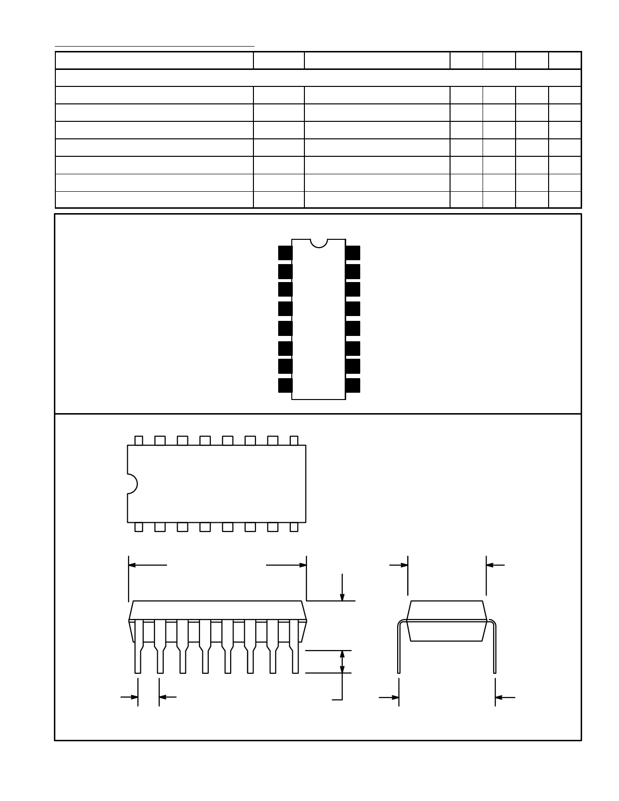
Pin Connection Diagram
Transformer Demagnetizatin
Sensing Input
1
Secondary Pulses Input 2
Power Transistor Current
Limitation Input
3
GND 4
16 Power Supply
15 Positive Output Stage Supply
14 Power Output
13 GND
GND 5
12 GND
Error Amplifier Input (Inverting) 6
11 Oscillator Resistor
Error Amplifier Output 7
10 Oscillator Capacitor
Overload Integration Capacitor 8
9 Soft–Start Capacitor
16
9
1
8
.787 (20.0) Max
.201
(5.1)
.100 (2.54) .130 (3.3) Min
.280 (7.1)
.335 (8.5)
Share Link: 