MAX779LC 데이터 시트보기 (PDF) - Maxim Integrated
부품명
상세내역
제조사
MAX779LC Datasheet PDF : 12 Pages
| |||
Low-Voltage Input, 3V/3.3V/5V/
Adjustable Output, Step-Up DC-DC Converters
VIN
C1
22µF
LI
22µH
5
2 IN
LX
6
OUT
7
MAX779L
SHDN
R1
C3
1
ILIM
AGND
8
FB
PGND
3
4
R2
VOUT
C2
100µF
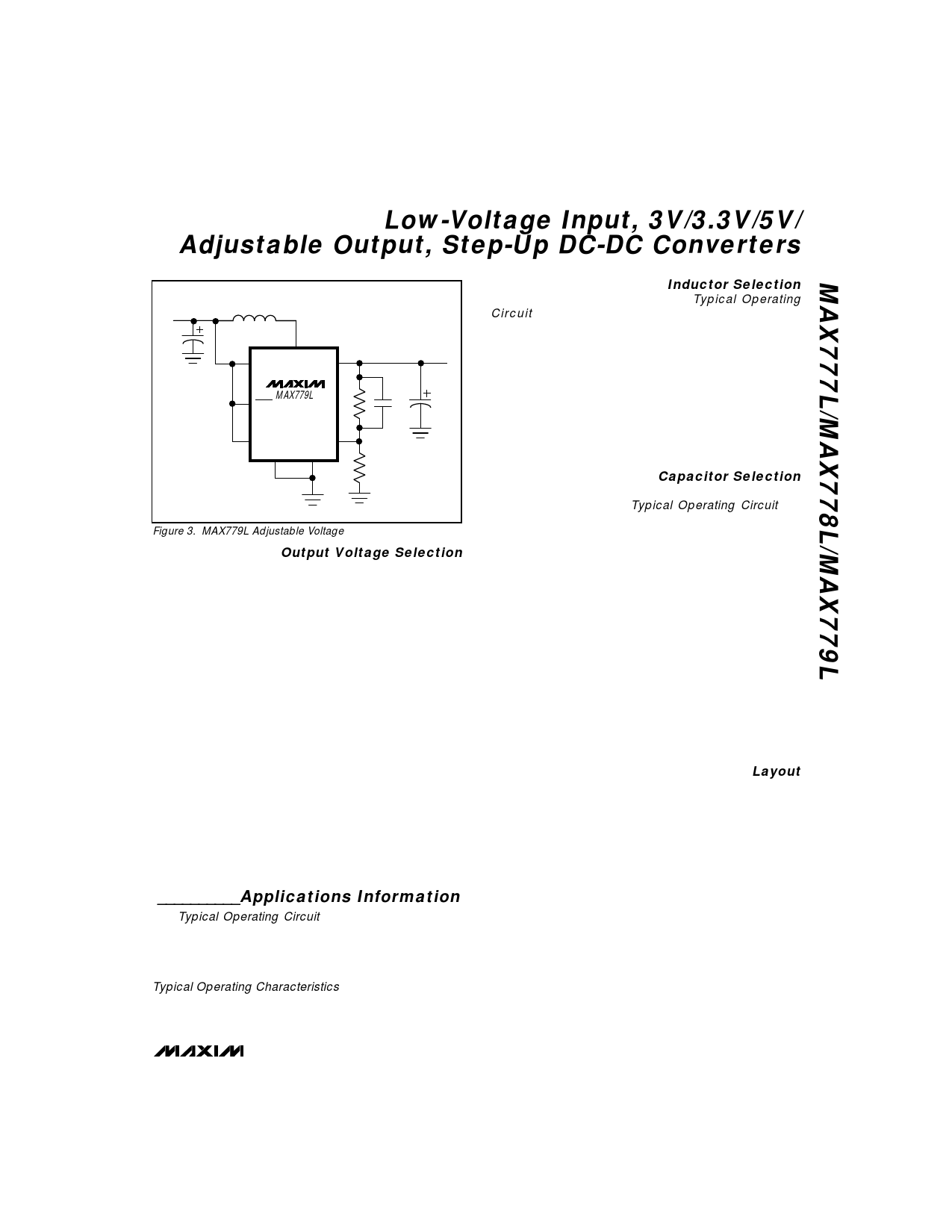
Figure 3. MAX779L Adjustable Voltage
Output Voltage Selection
The output voltage of the MAX777L is fixed at 5V. The
MAX778L output voltage can be set to 3V by leaving the
SEL pin open. Connect SEL to AGND for 3.3V operation.
The MAX779L’s output voltage is set by two resistors,
R1 and R2 (Figure 3), which form a voltage divider
between the output and the FB pin. The output voltage
can be set from 2.5V to 6.0V by the equation:
VOUT = (0.2025) [(R1 + R2)/R2]
To simplify the resistor selection:
R1 = (R2)[(VOUT/0.2025) - 1]
Since the input current at FB is 40nA maximum, large val-
ues (10kΩ to 50kΩ for R2) can be used with no significant
loss of accuracy. For 1% error, the current through R2
should be at least 100 times FB’s bias current.
When large values are used for the feedback resistors
(R1 > 50kΩ), stray output impedance at FB can add
“lag” to the feedback response, destabilizing the regula-
tor and creating a larger ripple at the output. Lead
lengths and circuit board traces at the FB node should be
kept short. Reduce ripple by adding a “lead” compensa-
tion capacitor (C3, 100pF to 50nF) in parallel with R1.
__________Applications Information
The Typical Operating Circuit shows a MAX777L step-
up application circuit. This circuit starts up and oper-
ates with inputs ranging from 1.0V to 4.5V. Start-up time
is a function of the load, typically less than 5ms. Output
current capability is a function of the input voltage. See
Typical Operating Characteristics.
Inductor Selection
The 22µH inductor shown in the Typical Operating
Circuit is sufficient for most MAX777L/MAX778L/
MAX779L designs. Other inductor values ranging from
10µH to 47µH are also suitable. The inductor should
have a saturation rating equal to or greater than the
peak switch-current limit, which is 1A without an exter-
nal current limit (ILIM connected to IN). It is acceptable
to operate the inductor at 120% of its saturation rating;
however, this will reduce efficiency. For highest effi-
ciency, use an inductor with a low DC resistance,
preferably under 0.2Ω. Table 1 lists suggested inductor
suppliers.
Capacitor Selection
The 100µF, 10V surface-mount tantalum (SMT) output
capacitor shown in the Typical Operating Circuit will
provide a 20mV output ripple or less, stepping up from
2V to 3.3V at 200mA. Smaller capacitors, down to 10µF,
are acceptable for light loads or in applications that tol-
erate higher output ripple. The input capacitor may be
omitted if the input lead length is less than 2 inches
(5cm) or if the loads are small.
The primary factor in selecting both the output and
input filter capacitor is low ESR. The ESR of both
bypass and filter capacitors affects efficiency. Optimize
performance by increasing filter capacitors or using
specialized low-ESR capacitors. The smallest low-ESR
SMT tantalum capacitors currently available are
Sprague 595D or 695D series. Sanyo OS-CON organic
semiconductor through-hole capacitors also exhibit
very low ESR, are rated for the wide temperature range,
and are particularly useful for operation at cold temper-
atures. Table 1 lists suggested capacitor suppliers.
Layout
The MAX777L/MAX778L/MAX779L’s high peak currents
and high-frequency operation make PC layout impor-
tant for minimum ground bounce and noise. Locate
input bypass and output filter capacitors close to the
device pins. All connections to the FB pin (MAX779L)
should also be kept as short as possible. A ground
plane is recommended. Solder AGND (pin 3) and
PGND (pin 4), directly to the ground plane. Refer to the
MAX777L/MAX778L/MAX779L evaluation kit (EV kit)
manual for a suggested surface-mount layout.
_______________________________________________________________________________________ 9
Share Link: 