VS-SD200N24PC 데이터 시트보기 (PDF) - Vishay Semiconductors
부품명
상세내역
제조사
VS-SD200N24PC Datasheet PDF : 8 Pages
| |||
www.vishay.com
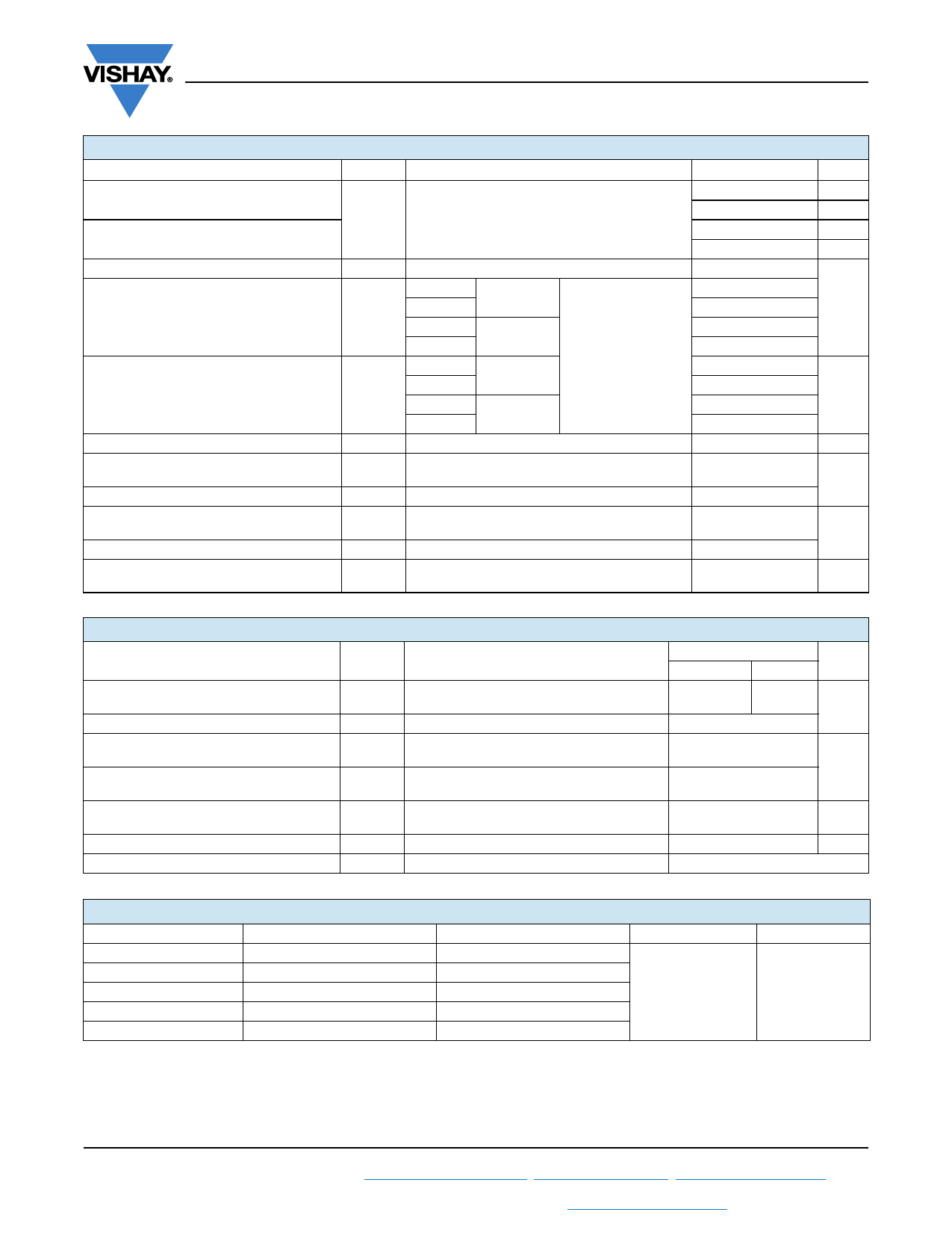
VS-SD200N/R Series
Vishay Semiconductors
FORWARD CONDUCTION
PARAMETER
Maximum average forward current
at case temperature
Maximum average forward current
at case temperature
Maximum RMS forward current
Maximum peak, one-cycle forward,
non-repetitive surge current
SYMBOL
IF(AV)
IF(RMS)
IFSM
Maximum I2t for fusing
I2t
Maximum I2Öt for fusing
Low level value of threshold voltage
High level value of threshold voltage
Low level value of forward slope resistance
High level value of forward slope resistance
Maximum forward voltage drop
I2Öt
VF(TO)1
VF(TO)2
rf1
rf2
VFM
TEST CONDITIONS
180° conduction, half sine wave
DC at 95 °C case temperature
t = 10 ms No voltage
t = 8.3 ms reapplied
t = 10 ms
t = 8.3 ms
t = 10 ms
t = 8.3 ms
100 % VRRM
reapplied
No voltage
reapplied
Sinusoidal half wave,
initial
TJ = TJ maximum
t = 10 ms 100 % VRRM
t = 8.3 ms reapplied
t = 0.1 to 10 ms, no voltage reapplied
(16.7 % x x IF(AV) < I < x IF(AV)),
TJ = TJ maximum
(I > x IF(AV)), TJ = TJ maximum
(16.7 % x x IF(AV) < I < x IF(AV)),
TJ = TJ maximum
(I > x IF(AV)), TJ = TJ maximum
Ipk = 630 A, TJ = TJ maximum,
tp = 10 ms sinusoidal wave
VALUES
200
110
220
100
314
4700
4920
3950
4140
110
101
78
71
1100
0.90
1.00
0.79
0.64
1.40
UNITS
A
°C
A
°C
A
kA2s
kA2Ös
V
mW
V
THERMAL AND MECHANICAL SPECIFICATIONS
PARAMETER
SYMBOL
TEST CONDITIONS
SD200N/R
1600 to 2000 2400
UNITS
Maximum junction operating
temperature range
Maximum storage temperature range
Maximum thermal resistance,
junction to case
Maximum thermal resistance,
case to heatsink
TJ
TStg
RthJC
RthCS
DC operation
Mounting surface, smooth, flat and greased
-40 to 180 -40 to 150
°C
-55 to 200
0.23
K/W
0.08
Maximum allowed
mounting torque ± 10 %
Not-lubricated threads
14
Nm
Approximate weight
120
g
Case style
See dimensions (link at the end of datasheet)
DO-30 (DO-205AC)
RthJC CONDUCTION
CONDUCTION ANGLE SINUSOIDAL CONDUCTION
180°
0.041
120°
0.049
90°
0.063
60°
0.093
30°
0.156
RECTANGULAR CONDUCTION TEST CONDITIONS
0.030
0.051
0.068
0.096
TJ = TJ maximum
0.157
UNITS
K/W
Note
• The table above shows the increment of thermal resistance RthJC when devices operate at different conduction angles than DC
Revision: 11-Jan-18
2
Document Number: 93541
For technical questions within your region: DiodesAmericas@vishay.com, DiodesAsia@vishay.com, DiodesEurope@vishay.com
THIS DOCUMENT IS SUBJECT TO CHANGE WITHOUT NOTICE. THE PRODUCTS DESCRIBED HEREIN AND THIS DOCUMENT
ARE SUBJECT TO SPECIFIC DISCLAIMERS, SET FORTH AT www.vishay.com/doc?91000
Share Link: 