SLA7024 데이터 시트보기 (PDF) - Sanken Electric co.,ltd.
부품명
상세내역
제조사
SLA7024 Datasheet PDF : 7 Pages
| |||
2-Phase Stepper Motor Unipolar Driver ICs (2-Phase/1-2 Phase Excitation)
Application Notes
SLA7027MU/SLA7024M/SLA7026M
sDetermining the Output Current
Fig. 1 shows the waveform of the output current (motor coil cur-
rent). The method of determining the peak value of the output
current (IO) based on this waveform is shown below.
(Parameters for determining the output current IO)
Vb: Reference supply voltage
r1,r2: Voltage-divider resistors for the reference supply voltage
RS: Current sense resistor
(1) Normal rotation mode
IO is determined as follows when current flows at the maximum
level during motor rotation. (See Fig.2.)
IO ≅ r2 • Vb ................................................................ (1)
r1+r2 RS
(2) Power down mode
The circuit in Fig.3 (rx and Tr) is added in order to decrease the
coil current. IO is then determined as follows.
IOPD ≅
1
r1(r2+rX)
1+ r2 • rX
• .V..b...................................................... (2)
RS
Equation (2) can be modified to obtain equation to determine rx.
rX=
1
r1
1
Vb −1
Rs • IOPD
1
−
r2
Fig. 4 and 5 show the graphs of equations (1) and (2) respec-
tively.
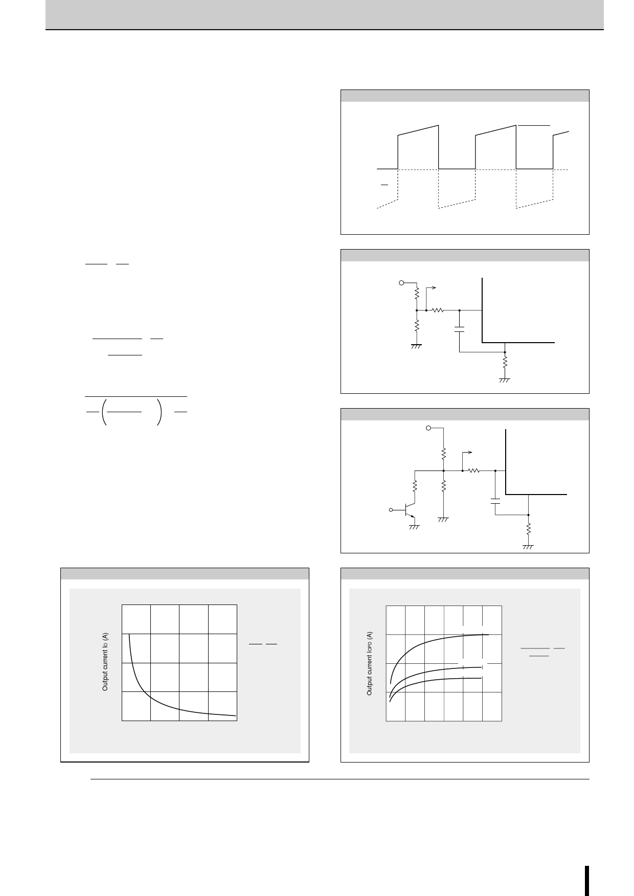
Fig. 1 Waveform of coil current (Phase A excitation ON)
IO
Phase A
0
Phase A
Fig. 2 Normal mode
Vb(5V)
r1
r2
r6
r5
C3
3,(14)
9,(10)
RS
Fig. 3 Power down mode
Vb(5V)
r1
rX
r2
Power down
signal
Tr
r6
r5
3,(14)
9,(10)
C3
Fig. 4 Output current IO vs. Current sense resistor RS
4
3
IO= r2 · Vb
r1+r2 RS
r1=510Ω
2
r2=100Ω
rx=∞
Vb=5V
1
0
0
1
2
3
4
Current sense resistor RS (Ω)
Fig. 5 Output current IOPD vs. Variable current sense resistor rx
2.0
1.5
RS =0.5Ω
1.0
RS =0.8Ω
IOPD=
1
1+r1r(2r2· +rrXX)
· Vb
RS
r1=510Ω
RS =1Ω
r2=100Ω
Vb=5V
0.5
00 200 400 600 800 1000 1200
Variable current sense resistor rX (Ω)
(NOTE)
Ringing noise is produced in the current sense resistor RS when
the MOSFET is switched ON and OFF by chopping. This noise
is also generated in feedback signals from RS which may there-
fore cause the comparator to malfunction. To prevent chopping
malfunctions, r5(r6) and C3(C4) are added to act as a noise filter.
However, when the values of these constants are increased,
the response from RS to the comparator becomes slow. Hence
the value of the output current IO is somewhat higher than the
calculated value.
SLA7027MU/SLA7024M/SLA7026M 23
Share Link: 