NVD0.1CKK-M6 데이터 시트보기 (PDF) - Power-One Inc.
부품명
상세내역
제조사
NVD0.1CKK-M6 Datasheet PDF : 11 Pages
| |||
NV Series: 4 - 6W DC/DC Converters
9-36V, 18-36V, 36-72V & 16-75V Inputs
3.3V, 5.0V, 12V, 15V, ±5.0V, ±12V, ±15V & ±24V Outputs
Product Specifications
Oct 2001
Surface Mount Assembly
Soldering:
The following instructions must be observed when
soldering the unit. Failure to observe these
instructions may result in failure or significant
degradation of the module performance. Power-
One will not honor any warranty claims arising
from failure to observe these instructions.
This product is approved for forced convection
reflow soldering only.
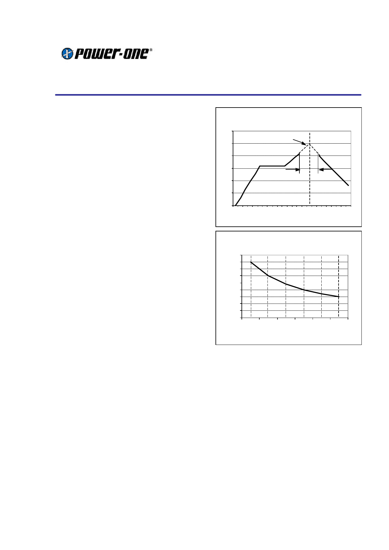
The curves below define the maximum peak
reflow temperature permissible measured on
Pins 1 and 10 of the converter.
The lead-frame is constructed for a high
temperature glass filled, UL94V0 flame retardant,
diallyl ortho-phthalate moulding com pound
commonly used for packaging of electronics
components. It has passed NASA outgassing
tests and is certified to MIL-M-14. The coefficient
of thermal expansion is equivalent to FR4.
The gull wing leads are formed to ensure optimal
solder joint strength and structure. Furthermore
they facilitate optical inspection (manual or
automatic). The leads are formed from a 97% Cu
alloy plated with Cu and Sn 90. This material is
commonly used in the manufacture of integrated
circuits. It has good corrosion resistance and
exhibits the nobility inherent to all high copper
alloys. Unlike brasses, this material is essentially
immune to stress corrosion cracking. It also
exhibits excellent solderability. It is readily
wetted by solders and performs well in standard
solderability tests. (Dip of Class II or better).
The product is manufactured with a patented
process, which is fully automated, and ‘in-line’.
This ensures that there is no contamination or
mechanical stress on the lead-frame so that the
co planarity and solderability are maintained.
The product is shipped in JEDEC trays to
guarantee preservation of the co-planarity and
enable fully automated assembly in the final
application.
.
Max. temp. on pins 1 and 10 during reflow
soldering (deg C)
300
Peak Temperature
(See fig below)
250
200
150
tp
100
50
0
190 – 450 s
Time (s)
Restriction curve above 215ºC
Peak temp. at pins 1 and 10 (ºC)
245
240
235
230
225
220
215
210
205
200
10 20 30 40 50 60
tp (s)
Pick & Place Assembly:
The product is designed with a large flat area in
the center of the top surface to serve as a pick up
point for automated vacuum pick and place
equipment. The ‘open board’ construction of the
unit ensures that weight is kept to a minimum.
However due to the relatively large size of the
component, a large nozzle (> 2.0mm, depending
on vacuum pressure) is recommended for picking
and placing.
The unit may also be automatically handled using
‘odd-form’ placement equipment, with mechanical
grippers. For this type of equipment the end
edges of the device, which have no leads and
also feature the greatest dimensional accuracy,
should be used as pick-up points.
18-Oct-01
Rev 1.0
www.power-one.com
Page 8 of 11
Share Link: 