AN17820B 데이터 시트보기 (PDF) - Panasonic Corporation
부품명
상세내역
제조사
AN17820B
Panasonic Corporation

AN17820B Datasheet PDF : 16 Pages
| |||
AN17820B
Technical Data (continued)
y Application information
1. Supply decoupling
To ensure a stable supply and achieve better ripple rejection, decoupling capacitors need to be connected to VCC (Pin 1).
Decoupling capacitors should have small equivalent series resistance (ESR). This is to prevent resistive losses and
introduction of undesirable phase shift to internal circuit.
A ceramic capacitor of 100 nF in parallel with a non-ceramic (tantalum or aluminum electrolytic) capacitor of 470 μF are
suggested. This combination has a small ESR over a wide frequency range.
Although small in size and ESR, large valued ceramic capacitor is not advisable to use. Current surges during power On/Off
might store energy in the inductances of the power leads, and a large voltage spike could be created when the stored energy is
/ transferred from the inductances to the ceramic capacitor. The amplitude of the spike could exceed twice the supply voltage.
e . ESR
c ge Fig. 1. Practical capacitor
ta C
n d ycle s 2. Standby operation
a e lifec Standby pin should be connected with carefully selected components in order to avoid "pop noise" during Standby On/Off
t transient.
n u uc The 68 kΩ resistor and 10 μF capacitor pair can delay the rising of voltage at pin 5 to reach the Standby threshold. When
rod standby is switching on together with supply, this delay would be very useful to ensure no "pop noise".
P If the standby voltage is provided by a microcontroller, the suppression of "Pop" could even be better.
te tin ur The microcontroller can set a delay of 100 ms to 200 ms between the supply and Standby On/Off.
g fo e . The 68 kΩ and 270 kΩ resistor also from a voltage divider, which determines the Standby threshold.
win typ tion VCC
in n follo ance pe ed rma 5
STB
es ten ty typ fo / 68 kΩ
STB
a coed incluedd maintenancetinued type test in .jp/en 270 kΩ
10 μF
Output
M is tinu plan main discontinued about lasonic.co Fig. 2. Standby circuit
Fig. 3. Standby On/Off logic
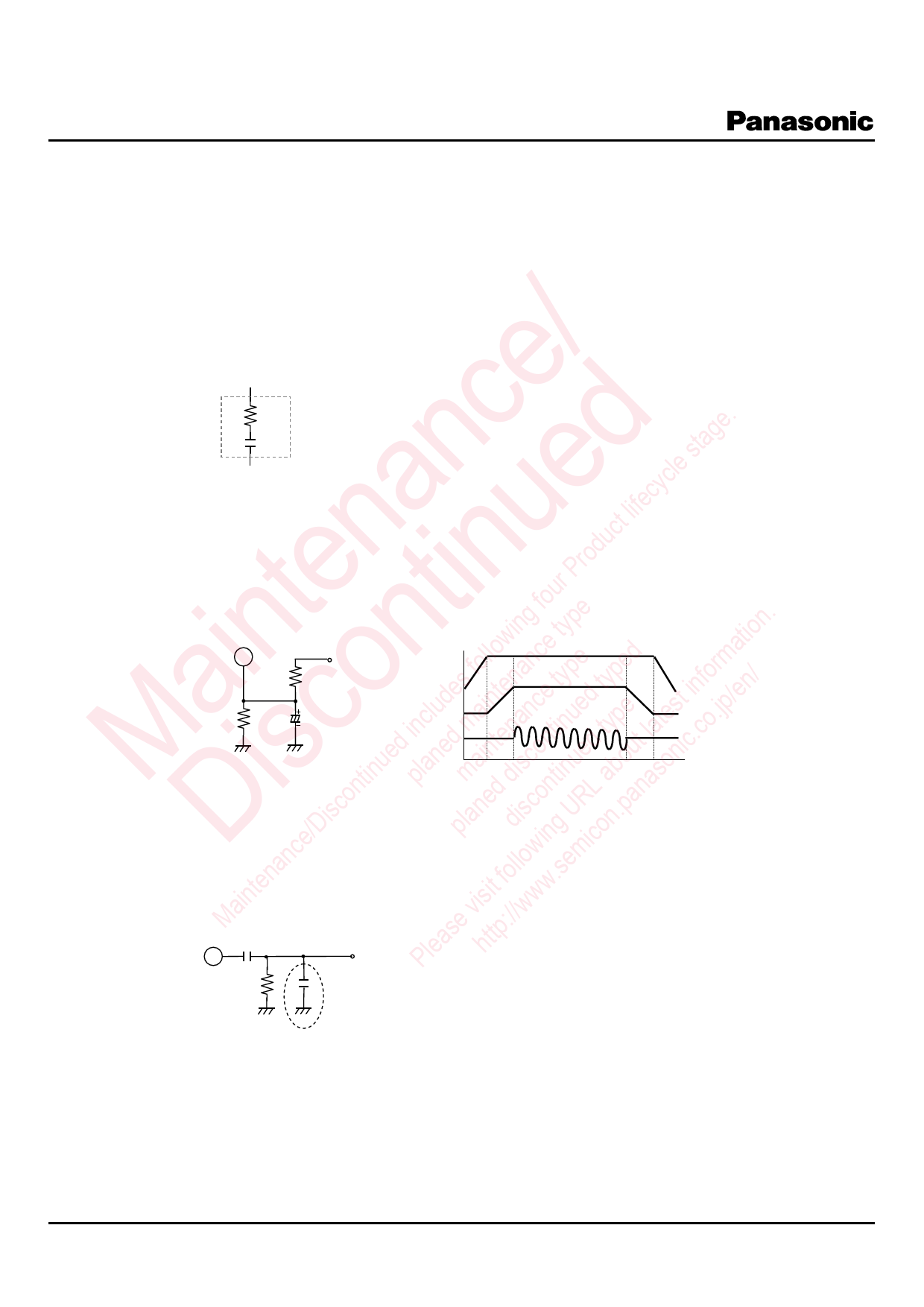
e/Discon planed discoinng URLon.pana 3. Input DC decoupling
D ic Before the input signal reaches differential amplifier stage, its DC component should be remove.
anc llow em The capacitor of 1 μF pass only AC signal and the 10 kΩ resistor forms a DC path to ground.
inten it fo w.s The 1 nF capacitor in parallel to the 10 kΩ resistor is optional and it serves to filter out high frequency noise at the input.
Ma ase visttp://ww 1 μF
Ple h 6
Vin
10 kΩ
1 nF
Fig. 4. Input DC decoupling
SDB00167BEB
10
Share Link: