NTE870 데이터 시트보기 (PDF) - NTE Electronics
부품명
상세내역
제조사
NTE870 Datasheet PDF : 3 Pages
| |||
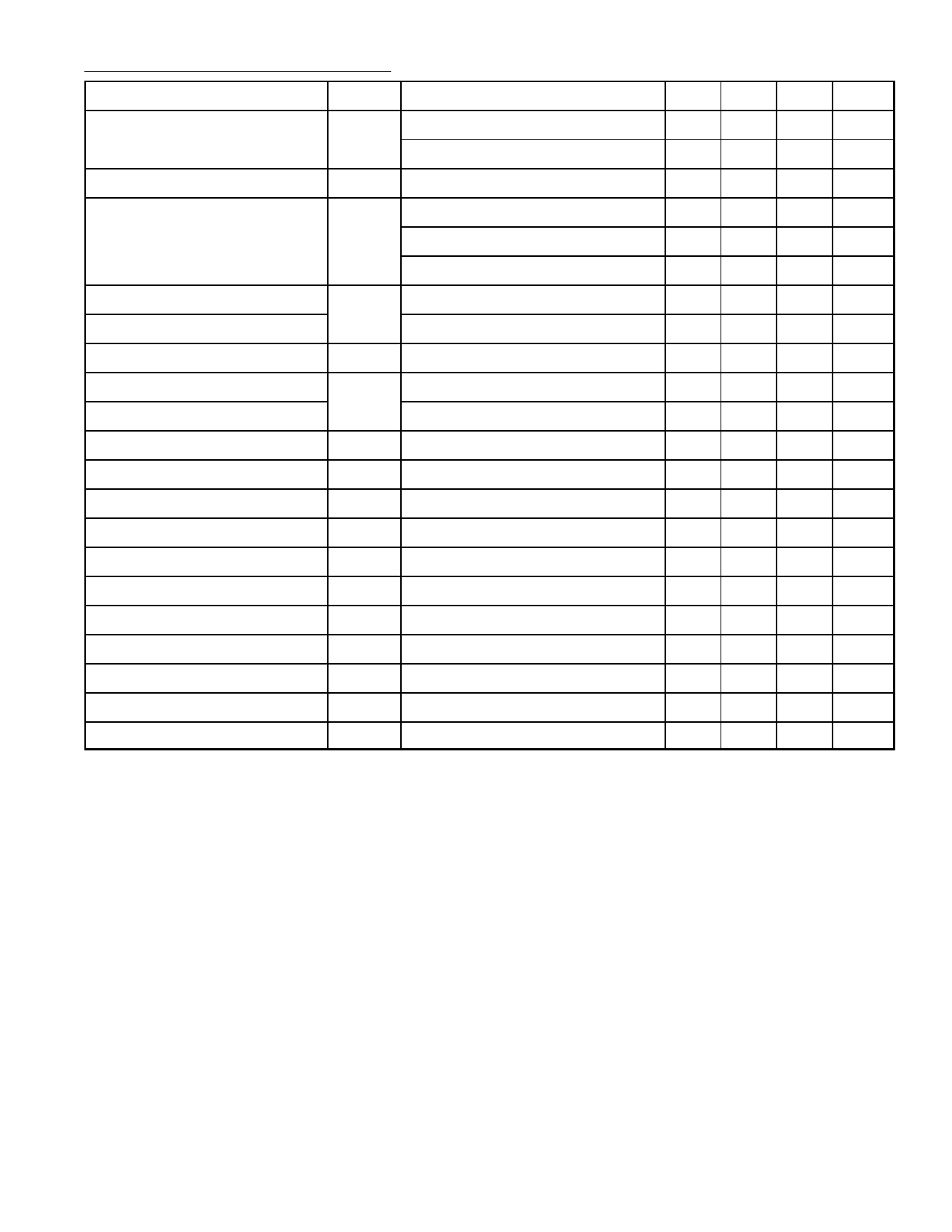
Electrical Characteristics (Cont’d): (TA = +25°C, V+/V– = ±15V, IABC = 500µA)
Parameter
Symbol
Test Conditions
Min Typ Max Unit
Forward Transconductance (gm) gm
6700 9600 13000 µmhos
gm Tracking
Peak Output Current
TA = –20° to +75°C
RL = 0, IABC = 5µA
IOP RL = 0, IABC = 5µA
RL = 0, IABC = 500µA
RL = 0, TA = –20° to +75°C
5400 –
–
0.3
–
5.0
350 500
300 –
– µmhos
–
dB
–
µA
650 µA
–
µA
Peak Output Voltage Positive
VOP RL = ∞, 5µA ≤ IABC ≤ 500µA
+12 ±14.2 –
V
Peak Output Voltage Negative
Supply Current
VOS Sensitivity Positive
VOS Sensitivity Negative
Input Offset Current
ICC
SVR
IIO
RL = ∞, 5µA ≤ IABC ≤ 500µA
IABC = 500µA, two circuit
∆VOS/∆V+
∆VOS/∆V–
–12 –14.4 –
V
–
2.6
–
mA
76.5 94.0 –
dB
76.5 94.0 –
dB
–
0.1 0.6
µA
CMMR
CMR
80 110 –
dB
Common Mode Range
VICM
±12.0 ±13.5 –
V
Cross Talk
CT 20Hz < f < 20kHz, Note 2
– –100 100 dB
Differential Input Current
IID IABC = 0, Input = ±4V
– 0.02 100 nA
Leakage Current
Input Resistance
ILEAK
RIN
IABC = 0
–
0.2
0
nA
10 26
–
kΩ
Open Loop Bandwidth
–
2
– MHz
Slew Rate
SR
–
50
– V/µs
Buffer Input Current
Note 2
–
0.4 5.0
µA
Peak Buffer Output Voltage
Note 2
10
–
–
V
Note 1. Open unless otherwise specified. The inputs to the buffers are grounded and the outputs
are open.
Note 2. ROUT = 5kΩ connected from the buffer output to V– and the input buffer is connected to
the transconductance amplifier output. IABC = 500µA.
Share Link: 