NTE7083 데이터 시트보기 (PDF) - NTE Electronics
부품명
상세내역
제조사
NTE7083 Datasheet PDF : 3 Pages
| |||
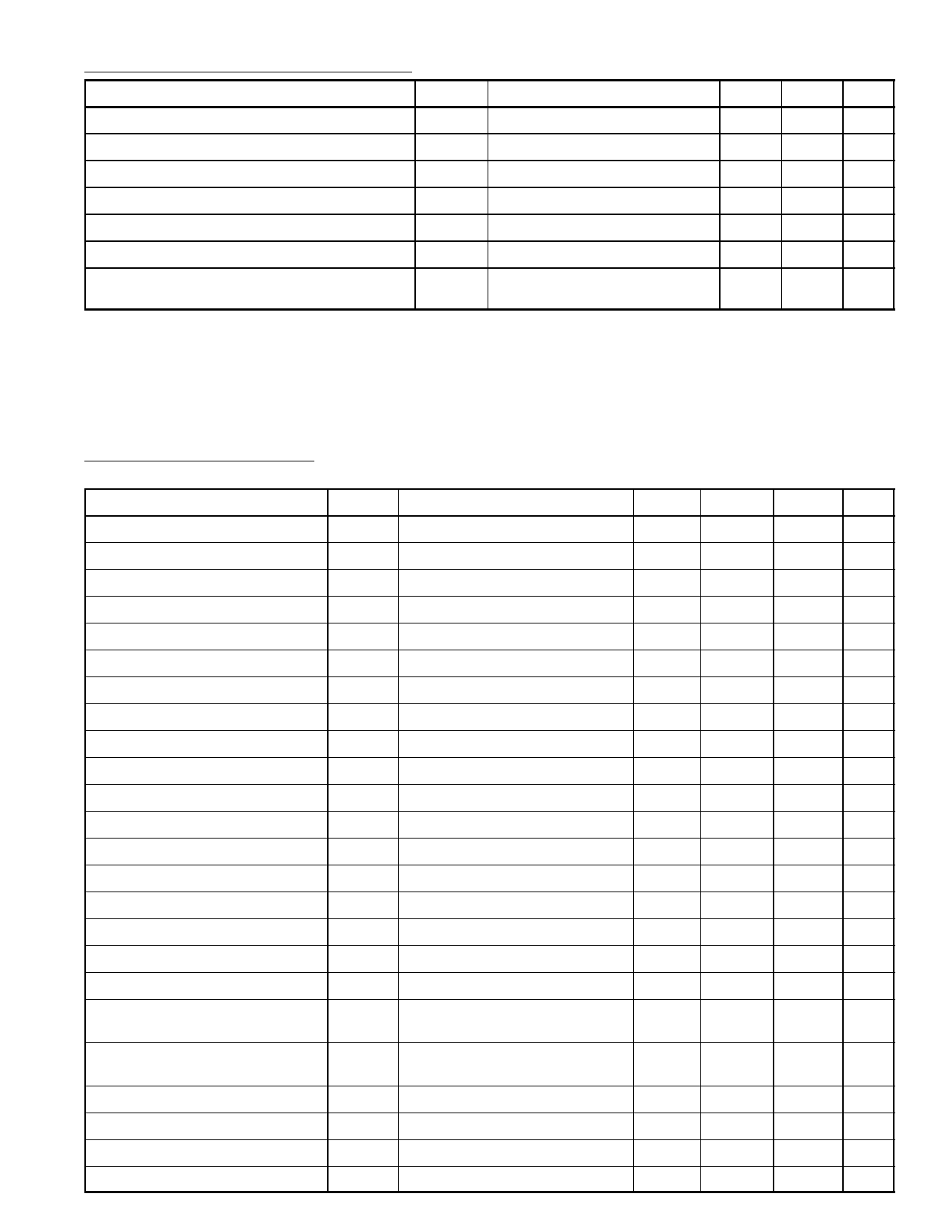
Absolute Maximum Ratings (Cont’d):
Parameter
Symbol
Test Conditions
Storage Temperature Range
Operating Ambient Temperature Range
Maximum Junction Temperature
Tstg
TA
TJmax
Note 2
Note 3
Total Power Dissipation
Ptot Note 2
ESO Stability
VESO Note 4
Thermal Resistance, Junction–to–Ambient
Thermal Resistance, Junction–to–Mounting
Base
RthJA
RthJMB
Min Max Unit
–25 +150 °C
–20 +70 °C
–
+150 °C
–
–
W
–2000 +2000 V
–
20 K/W
–
5 K/W
Note 2. The maximum value to the operating ambient temperature range and the power dissipation
depends on the heatsink.
Note 3. Internally liminted by thermal protection: switching temperature point at TJ = +150°C ±8°C.
Note 4. Human body model: 1.5kΩ, 100pF, 5 pulses.
Electrical Characteristics: (All voltages are measured to VGND (Pin8), TA = +25°C, VP = +23V
unless otherwise specified)
Parameter
Symbol
Test Conditions
Min
Typ
Max Unit
Supply Voltage Range (Pin10)
Supply Voltage Range (Pin6)
Supply Current
Supply Current
Supply Current
Minimum Output Voltage
Maximum Output Voltage
Output Voltage During Flyback
Output Current
Output Current
Preamplifier Input Current
Stabilized Voltage
Blanking Pulse Output Voltage
Blanking Pulse Output Resistance
Blanking Pulse Output Current
Blanking Pulse Duration
Output Voltage Ramp Generator
Output Current Ramp Generator
Output Voltage Frequency Detec-
tor
VP
10
–
45
V
VP
10
–
30
V
I10 V10 = 25V, V5 = 3V without load
–
12
–
mA
I6 V6 = 25V, V5 = 1V without load
–
20
–
mA
I6 V6 = 25V, V5 = 3V withput load
–
5
–
mA
V7 I7 = 1A
–
1.40
1.65
V
V7 I7 = 1A
V6 –2.3 V6 –2.0
–
V
V9 I9 = –1A
–
V10 –2.2
–
V
I7
–
–
±1.3
A
I8
–
–
±1.3
A
I5
–
–0.1
–
µA
V1
6.1
6.8
7.3
V
V3
–
5.7
–
V
R3
–
300
–
Ω
I3
0
–
–3 mA
tbl R = 100Ω, C = 10pF (Pin12)
640
680
730 µs
V11
0.3
–
20
V
I11
–2
–
15 x 103 µA
V13 Lower Frequency I13 = 1mA
–
–
1.0
V
Leakage Current Frequency
Detector
I13 Higher Frequency V13 = 50V
–
–
1.0
µA
Output Voltage Buffer Stage
Output Current Buffer Stage
Synchronizing Input Voltage
Synchronizing Input Voltage
V4
I4
V3 Positive Sync
V3 Negative Sync
0
–
20
V
–
–
–4.0 mA
1.0
–
6.0
V
–0.5
–
–0.7 V
Share Link: 