CX74036 데이터 시트보기 (PDF) - Conexant Systems
부품명
상세내역
제조사
CX74036 Datasheet PDF : 13 Pages
| |||
CX74036
Receive RF IC
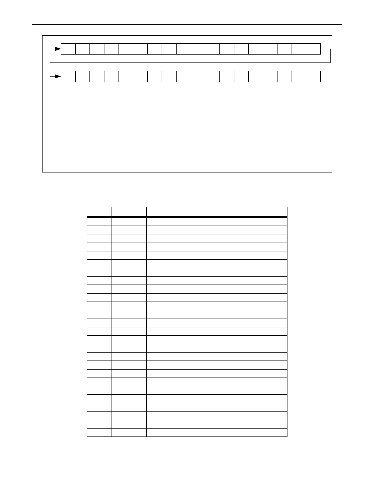
MSB
35
34
33
32
31
30
29
28
27
26
25
24
23
22
21
20
19
18
SPD A2B1 A2B0 M2B7 M2B6 M2B5 M2B4 M2B3 M2B2 M2B1 M2B0 CPP RB10 RB9 RB8 RB7 RB6 RB5
LSB
17
16
15
14
13
12
11
10
09
08
07
06
05
04
03
02
01
00
RB4 RB3 RB2 RB1 RB0 AB3 AB2 AB1 AB0 MB7 MB6 MB5 MB4 MB3 MB2 MB1 MB0 VRS
00 = First bit shifted in (LSB)
35 = Last bit shifted in (MSB)
VRS = Select VCO or Reference Input to Programmable Counter
"0" = Reference Input
"1" = VCO Input
MB0 - MB7: Programming for Synthesizer M Counter: MB0 (LSB), MB7 = (MSB)
AB0 - AB3: Programming for Synthesizer A Counter: AB0 (LSB), AB7 = (MSB)
RB0 - RB10: Programming for Synthesizer R Counter: RB0 (LSB), RB10 = (MSB). CPP = Change Pump Polarity,
"0" = Ground Reference
M2B0 - M2B7: Programming for LO Divider M Counter: M2B0 (LSB), M2B7 = (MSB)
A2B0 - A2B7: Programming for LO Divider A Counter: A2B0 (LSB), A2B1 = (MSB)
SPD = Synthesizer Power Down (for External Synthesizer Mode)
"1" = Internal Synthesizer,
"0"= External Synthesizer
101105A-4_101200
Figure 4. 3-Wire Programming Data Pattern
Table 3. Signal Pin Names and Definitions (1 of 2)
Pin No.
1
2
3
4
5
6
7
8
9
10
11
12
13
14
15
16
17
18
19
20
21
22
23
24
25
26
Signal Name
LNA_G
MXIH
MIXIL
BAND
CHIP_EN
LOIH
LOIL
VCC_MX
STANDBY
IQ/IF
MXOUT+
MXOUT-
MX2I+
MX2I-
VCC_IF
IFBYPASS
MX2OUT
Vvga
VCC_VGA
VGAI-
VGAI+
FB_CAP
LATCH_EN
CLK
DATA
REFIN
Description
LNAs gain control command
1900 MHz band mixer Input
800 MHz band mixer Input
800 MHz/1900 MHz band select command
Chip power down select command
1900 MHz RF mixer LO input
800 MHz RF mixer LO input
RF mixer VCC
Control signal to enable RF LO buffers and VHF synthesizer
I/Q or IF output select command
RF mixer output. Open Collector.
RF mixer output. Open Collector.
IF mixer input
IF mixer input
IF section VCC
IF mixer bias decoupling
IF mixer output
Analog voltage input for VGA gain control
VGA section VCC
VGA input
VGA input
VGA DC feedback filter capacitor connection
Enable input line for internal synthesizer programming
Serial clock input line for internal synthesizer programming
Serial data input line for internal synthesizer programming
19.44 MHz reference oscillator input. Requires VCC/2 DC bias.
4
Conexant – Proprietary
101105A
Data Subject to Change
October 17, 2000
Share Link: 