NCS1S2412SC 데이터 시트보기 (PDF) - Murata Power Solutions
부품명
상세내역
제조사
NCS1S2412SC Datasheet PDF : 8 Pages
| |||
NCS1 Series
Isolated 1W 4:1 Input Single Output DC/DC Converters
TEMPERATURE CHARACTERISTICS
Parameter
Operation
Storage
Case temperature rise above ambient
Conditions
100% Load, Nom VIN, Still Air
ABSOLUTE MAXIMUM RATINGS
Short-circuit protection (for SELV input voltages)
Control pin input voltage
Lead temperature 1.0mm from case for 10 seconds (to JEDEC JESD22-B106 ISS C)
Input voltage, NCS1 12V input types
Input voltage, NCS1 24V input types
APPLICATION NOTES
Maximum Output Capacitance
Maximum output capacitance should not exceed:
Output Voltage
V
3.3
5
12
Maximum Load Capacitance
μF
470
470
220
Min. Typ. Max. Units
-40
105
-50
125
°C
15
22
Continuous
18V Max
260°C
25V
40V
Start-up times
Typical start up times for this series, with a typical input voltage rise time of 2.2μs and output capacitance of 10μF, are shown in the table below. The product series will
start into the maximum output capacitance with increased start times.
Part No.
NCS1S1203SC
NCS1S1205SC
NCS1S1212SC
NCS1S2403SC
NCS1S2405SC
NCS1S2412SC
Start-up times
ms
6
9
20
12
7
12
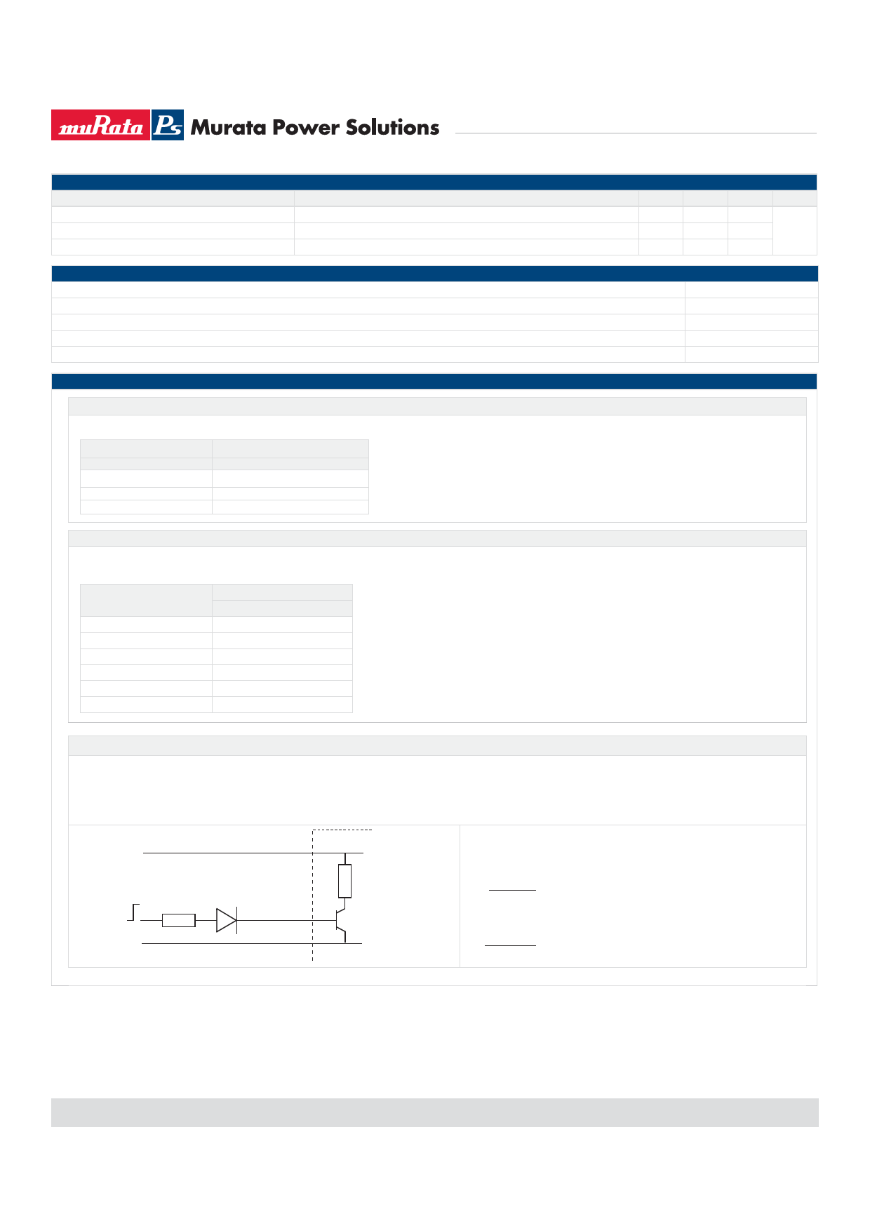
Control Pin
The NCS1 converters have a shutdown feature which enables the user to put the converter into a low power state. The control pin connects directly to the base of an internal
transistor, and the switch off mechanism for the NCS1 works by forward biasing this NPN transistor. If the pin is left open (high impedance), the converter will be ON (there is
no allowed low state for this pin), but once a control voltage is applied with sufficient drive current, the converter will be switched OFF. A suitable application circuit is shown
below.
V
IN
V
C
R
1
OV
-V
IN
NCS1
R
2
D
1 CTRL
Q
1
D (e.g. 1N4003) is required to provide high impedence when the signal is
1
low. From the NCS1 specification, the drive current to operate this function is
recommended to be 3mA, and hence the value of R can be derived as follows:
1
V -V -V
R=
1
CD
I
Q
C
Assuming V =5V, V =0.7V and V =1V:
C
D
Q
R=
1
5
- 0.7 - 1.0
3 x 10-3
=
1100Ω
www.murata-ps.com
All enquiries: www.murata-ps.com/support
KDC_NCS1.D01 Page 2 of 8
Share Link: 