MAX17411 데이터 시트보기 (PDF) - Maxim Integrated
부품명
상세내역
제조사
MAX17411
Maxim Integrated

MAX17411 Datasheet PDF : 72 Pages
| |||
Dual-Output, 3-/2-/1-Phase + 2-/1-Phase
Quick-PWM Controllers for VR12/IMVP7
ABSOLUTE MAXIMUM RATINGS
VCC, VDDA, VDDB to GND (AGND).........................-0.3V to +6V
VDIO, CLK, ALERT# to GND (AGND).....................-0.3V to +6V
CSPAAVE, CSPBAVE, CSP_,
CSN_ to GND (AGND).........................................-0.3V to +6V
FBA, FBB to GND (AGND)....................... -0.3V to (VCC + 0.3V)
SR, IMAX_ to GND (AGND) ..................... -0.3V to (VCC + 0.3V)
POKA, POKB, EN to GND (AGND).........................-0.3V to +6V
VR_HOT# to GND (AGND)......................................-0.3V to +6V
THERMA, THERMB to GND (AGND)........ -0.3V to (VCC + 0.3V)
GNDSA, GNDSB to GND (AGND)........................-0.3V to +0.3V
TON to GND...........................................................-0.3V to +26V
DRVPWMA to GND (AGND)................... -0.3V to (VDDA + 0.3V)
DRVPWMB to GND (AGND)................... -0.3V to (VDDB + 0.3V)
DLA_ to GND (PGND)............................ -0.3V to (VDDA + 0.3V)
DLB to GND (PGND).............................. -0.3V to (VDDB + 0.3V)
BSTA_ to VDDA......................................................-0.3V to +26V
BSTB to VDDB........................................................-0.3V to +26V
LXA_ to BSTA_.........................................................-6V to +0.3V
LXB to BSTB............................................................-6V to +0.3V
LX_ to GND (AGND).................................................-6V to +26V
DHA_ to LXA_.......................................-0.3V to (VBSTA_ + 0.3V)
DHB to LXB............................................ -0.3V to (VBSTB + 0.3V)
Continuous Power Dissipation (TA = +70NC)
40-Pin TQFN (derate 35.7mW/NC above +70NC)....2857.1mW
48-Pin TQFN (derate 37mW/NC above +70NC)..........2963mW
Operating Temperature Range......................... -40NC to +105NC
Junction Temperature......................................................+150NC
Storage Temperature Range............................ -65NC to +165NC
Lead Temperature (soldering, 10s).................................+300NC
Soldering Temperature (reflow).......................................+260NC
PACKAGE THERMAL CHARACTERISTICS (Note 1)
40 TQFN
Junction-to-Ambient Thermal Resistance (qJA)...........28°C/W
Junction-to-Case Thermal Resistance (qJC)...............1.6°C/W
48 TQFN
Junction-to-Ambient Thermal Resistance (qJA)...........27°C/W
Junction-to-Case Thermal Resistance (qJC)...............1.3°C/W
Note 1: Package thermal resistances were obtained using the method described in JEDEC specification JESD51-7, using a four-
layer board. For detailed information on package thermal considerations, refer to www.maxim-ic.com/thermal-tutorial.
Stresses beyond those listed under “Absolute Maximum Ratings” may cause permanent damage to the device. These are stress ratings only, and functional opera-
tion of the device at these or any other conditions beyond those indicated in the operational sections of the specifications is not implied. Exposure to absolute
maximum rating conditions for extended periods may affect device reliability.
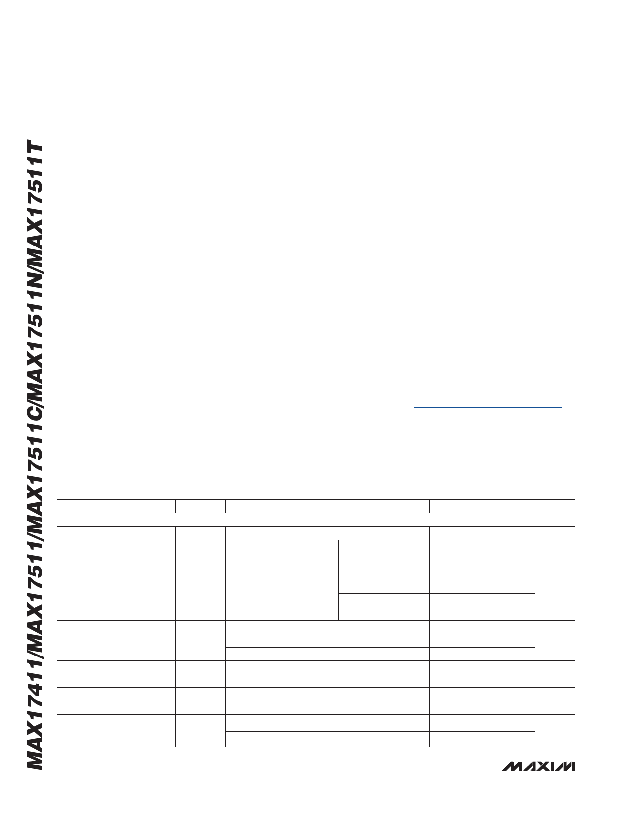
ELECTRICAL CHARACTERISTICS
(Circuits of Figures 1 and 2. VIN = 10V, VCC = VDDA = VDDB = 5V, EN = VCC, VGNDS_ = 0V, VFB_ = VCSP_AVE = VCSP_ = VCSN_
= 1V; [SerialVID = 1.00, FPWM MODE]; TA = 0°C to +85°C, unless otherwise noted. Typical values are at TA = +25NC. All devices
100% tested at TA = +25NC. Limits over temperature guaranteed by design.)
PARAMETER
SYMBOL
CONDITIONS
MIN TYP MAX UNITS
PWM CONTROLLER
Input Voltage Range
VCC, VDDA, VDDB
4.5
5.5
V
DC Output Voltage
Accuracy
Measured at FB_ with
DAC codes from
1.000V to 1.520V
-0.5
respect to GNDS_;
includes load regulation
DAC codes from
0.800V to 0.995V
-5
error (Note 2)
DAC codes from
0.250V to 0.795V
-8
+0.5
%
+5
mV
+8
Line Regulation Error
VSETTLED Bit Accuracy
VCC = 4.5V to 5.5V, VIN = 4.5V to 24V
Upward transitions
Downward transitions
0.1
mV
-15 -10
-5
mV
5
10
15
GNDS_ Input Range
-200
+200 mV
GNDS_ Gain
GNDS_ Input Bias Current
TON Shutdown Current
AGNDS
DVOUT/DVGNDS_
TA = +25NC
EN = GND, VIN = 24V, VCC = 0V, TA = +25NC
0.97 1.00 1.03 V/V
-0.5
+0.5
FA
0.01 0.1
FA
Boot Voltage
VBOOT
MAX17511N only, Reg A and Reg B
MAX17511C only, Reg B only
1.094 1.100 1.106
V
0.895 0.900 0.905
2 _______________________________________________________________________________________
Share Link: