EELXT905PC.C2 데이터 시트보기 (PDF) - Intel
부품명
상세내역
제조사
EELXT905PC.C2 Datasheet PDF : 38 Pages
| |||
LXT905 — Universal 10BASE-T Transceiver with 3.3V Support
Table 1. LXT905 Signal Descriptions (Continued)
LQFP
Pin #
PLCC
Pin #
Symbol
I/O
Description
16
18
LI
I
Link Enable. Controls link integrity test; enabled when LI is High, disabled
when LI is Low.
17
19
RBIAS
I
Bias Circuitry. A 7.5 kW 1% resistor to ground at this pin controls operating
circuit bias.
18
20
DSQE
SQE Disable. When DSQE is High, the SQE function is disabled.
I When DSQE is Low, the SQE function is enabled. SQE should be disabled for
normal operation in Hub/Switch/Repeater applications. Pulled Low internally1.
19
21
22
24
TPOP
TPON
O Twisted-Pair Outputs. Differential outputs to the twisted-pair cable. The
O outputs are pre-equalized.
23
25
24
26
MDO
MDI
I Mode Select 0 and 1. Mode select pins determine controller compatibility mode
I in accordance with Table 2. Pulled Low internally1.
25
27
26
28
TPIP
TPIN
I Twisted-Pair Inputs. A differential input pair from the twisted-pair cable.
I Receive filter is integrated on-chip. No external filters are required.
1. Externally pull-up or pull-down each pin separately using a 10k Ω, 1% termination resistor or tie directly to VCC or ground.
2. Do not allow this pin to float. If unused, tie High.
2.0
Functional Description
2.1
Introduction
The LXT905 Universal 10BASE-T Transceiver performs the physical layer signaling (PLS) and
Media Attachment Unit (MAU) functions, as defined by the IEEE 802.3 specification. It functions
as an integrated PLS/MAU for use with 10BASE-T twisted-pair networks.
The LXT905 interfaces a back-end controller to a twisted-pair (TP) cable. The controller interface
includes a transmit and receive clock and NRZ data channels, as well as mode control logic and
signaling. The twisted-pair interface comprises two circuits: Twisted-Pair Input (TPI) and Twisted-
Pair Output (TPO). In addition to the two basic interfaces, the LXT905 contains an internal crystal
oscillator and four LED drivers for visual status reporting.
Functions are defined from the back-end controller side of the interface. The LXT905 Transmit
function refers to data transmitted by the back-end to the twisted-pair network The LXT905
Receive function refers to data received by the back-end from the twisted-pair network. The
LXT905 performs all required functions defined by the IEEE 802.3 10BASE-T MAU
specification, such as collision detection, link integrity testing, signal quality error messaging,
jabber control, and loopback.
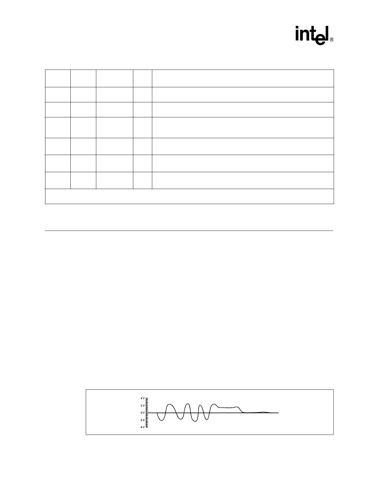
Figure 3. LXT905 TPO Output Waveform
10
Datasheet
Document #: 249271
Revision #: 002
Rev. Date: June 19, 2001
Share Link: 