MC44608P100G 데이터 시트보기 (PDF) - ON Semiconductor
부품명
상세내역
제조사
MC44608P100G Datasheet PDF : 15 Pages
| |||
MC44608
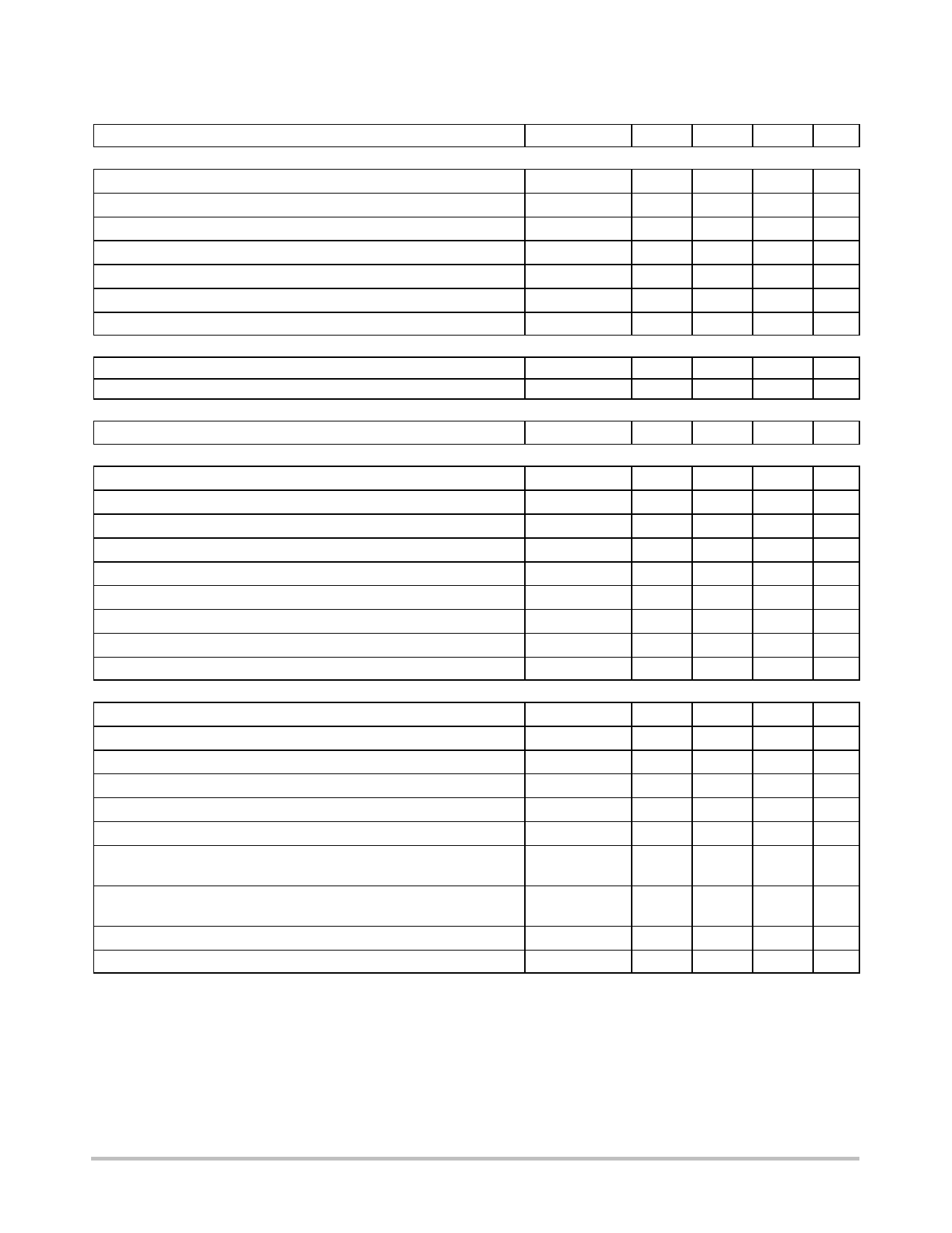
ELECTRICAL CHARACTERISTICS (VCC = 12 V, for typical values TA = 25C, for min/max values TA = --25C to +85C unless
otherwise noted) (Note 2)
Characteristic
Symbol
Min
Typ
Max Unit
DEMAGNETIZATION DETECTION section (note 3)
Demag Comparator Threshold (Vpin1 increasing)
Demag Comparator Hysteresis (Note 4)
Propagation Delay (Input to Output, Low to High)
Input Bias Current (Vdemag = 50 mV)
Negative Clamp Level (Idemag = --1.0 mA)
Positive Clamp Level @ Idemag = 125 mA
Positive Clamp Level @ Idemag = 25 mA
OVERTEMPERATURE section
Trip Level Over Temperature
Hysteresis
STANDBY MAXIMUM CURRENT REDUCTION section
Normal Mode Recovery Demag Pin Current Threshold
K FACTORS SECTION FOR PULSED MODE OPERATION
ICCS / Istup
MC44608P40
ICCS / Istup
MC44608P75
ICCL / Istup
(Vstup -- UVLO2) / (Vstup -- UVLO1)
(UVLO1 -- UVLO2) / (Vstup -- UVLO1)
ICS / Vcsth
Demag ratio Iovp / Idem NM
(V3 1.0 mA -- V3 0.5 mA) / (1.0 mA -- 0.5 mA)
Vcontrol Latchoff
SUPPLY SECTION
Minimum Startup Voltage
VCC Startup Voltage
Output Disabling VCC Voltage After Turn On
Hysteresis (Vstup--th -- Vuvlo1)
VCC Undervoltage Lockout Voltage
Hysteresis (Vuvlo1 -- Vuvlo2)
Absolute Normal Condition VCC Start Current @ (Vi = 100 V) and
(VCC = 9.0 V)
Switching Phase Supply Current (no load)
MC44608P40
MC44608P75
Vdmg--th
Hdmg
tPHL(In/Out)
Idem--lb
Vcl--neg--dem
Vcl--pos--dem--H
Vcl--pos--dem--L
30
--
--
--0.6
--0.9
2.05
1.4
Thigh
--
Thyst
--
Idem--NM
20
10 x K1
2.4
10 x K1
2.8
103 x K2
46
102 x Ksstup
1.8
102 x Ksl
90
106 x Ycstby
175
Dmgr
3.0
R3
--
V3
--
Vilow
Vstup--th
Vuvlo1
Hstup--uvlo1
Vuvlo2
Huvlo1--uvlo2
--(ICC)
ICCS
--
12.5
9.5
--
6.2
--
7.0
2.0
2.4
50
30
300
--
--0.7
2.3
1.7
160
30
25
2.9
3.3
52
2.2
120
198
4.7
1800
4.8
--
13.1
10
3.1
6.6
3.4
9.5
2.6
3.2
69
mV
--
mV
--
ns
--
mA
--0.4
V
2.8
V
1.9
V
--
C
--
C
30
mA
3.8
--
4.2
--
63
--
2.6
--
150
--
225
--
5.5
--
--
Ω
--
V
50
V
13.8
V
10.5
V
--
V
7.0
V
--
V
12.8
mA
3.6
mA
4.0
Latched Off Phase Supply Current
ICC--latch
0.3
0.5
0.68
mA
Hiccup Mode Duty Cycle (no load)
δHiccup
--
10
--
%
2. Adjust VCC above the startup threshold before setting to 12 V. Low duty cycle pulse techniques are used during test to maintain junction
temperature as close to ambient as possible.
3. This function can be inhibited by connecting pin 1 to GND.
4. Guaranteed by design (non tested).
http://onsemi.com
4
Share Link: 