MT88L85AN1 데이터 시트보기 (PDF) - Microsemi Corporation
부품명
상세내역
제조사
MT88L85AN1
Microsemi Corporation

MT88L85AN1 Datasheet PDF : 29 Pages
| |||
MT88L85
Data Sheet
capable of issuing symmetric bursts/pauses of predetermined duration. This burst/pause duration is 51 ms±1 ms
which is a standard interval for autodialer and central office applications. After the burst/pause has been issued, the
appropriate bit is set in the Status Register to indicate that the transmitter is ready for more data. The timing
described above is available when DTMF mode has been selected. However, when CP mode (Call Progress mode)
is selected, the burst/pause duration is doubled to 102 ms ±2 ms. Note that when CP mode and Burst mode have
been selected, DTMF tones may only be transmitted and not received. In applications where a non-standard
burst/pause time is desirable, a software timing loop or external timer can be used to provide the timing pulses
when the burst mode is disabled by enabling and disabling the transmitter.
Single Tone Generation
A single tone mode is available whereby individual tones from the low group or high group can be generated. This
mode can be used for DTMF test equipment applications, acknowledgment tone generation and distortion
measurements. Refer to Control Register B (CRB) description for details.
ACTIVE
INPUT
OUTPUT FREQUENCY (Hz)
SPECIFIED
ACTUAL
%ERROR
L1
697
699.1
+0.30
L2
770
766.2
-0.49
L3
852
847.4
-0.54
L4
941
948.0
+0.74
H1
1209
1215.9
+0.57
H2
1336
1331.7
-0.32
H3
1477
1471.9
-0.35
H4
1633
1645.0
+0.73
Table 2 - Actual Frequencies Versus Standard Requirements
Distortion Calculations
The MT88L85 is capable of producing precise tone bursts with minimal error in frequency (see Table 2). The
internal summing amplifier is followed by a first-order lowpass switched capacitor filter to minimize harmonic
components and intermodulation products. The total harmonic distortion for a single tone can be calculated by
using Equation 1, which is the ratio of the total power of all the extraneous frequencies to the power of the
fundamental frequency expressed as a percentage.
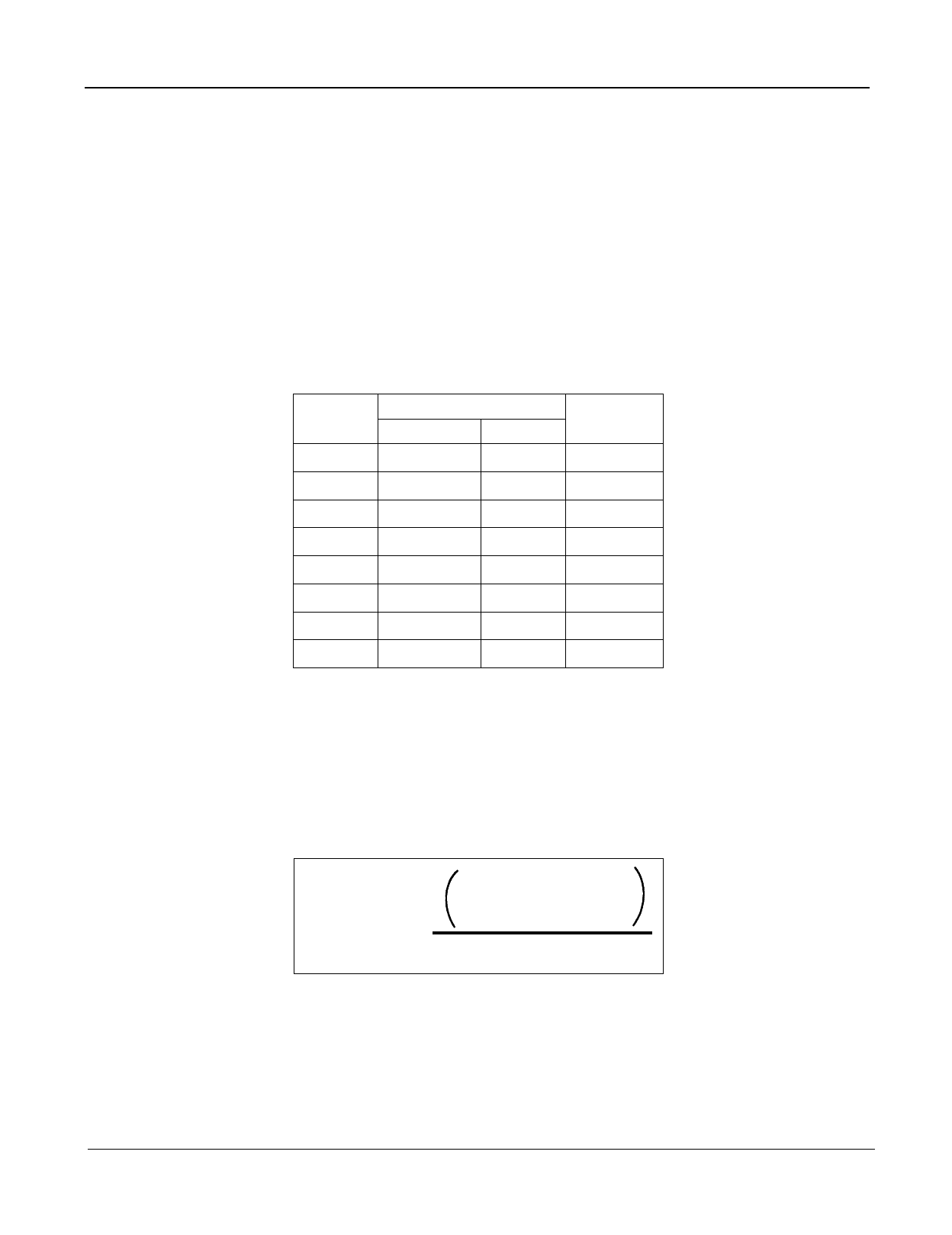
V22f + V23f + V24f + .... V2nf
THD (%) = 100
V2fundamental
Equation 1. THD (%) For a Single Tone
The Fourier components of the tone output correspond to V2f.... Vnf as measured on the output waveform. The total
harmonic distortion for a dual tone can be calculated by using Equation 2. VL and VH correspond to the low group
amplitude and high group amplitude, respectively and V2IMD is the sum of all the intermodulation components. The
internal switched-capacitor filter following the D/A converter keeps distortion products down to a very low level as
shown in Figure 9.
11
Zarlink Semiconductor Inc.
Share Link: