ADM705 데이터 시트보기 (PDF) - Analog Devices
부품명
상세내역
제조사
ADM705 Datasheet PDF : 12 Pages
| |||
ADM705/ADM706/ADM707/ADM708
CIRCUIT INFORMATION
POWER-FAIL RESET OUTPUT
RESET is an active low output that provides a reset signal to
the microprocessor whenever the VCC input is below the reset
threshold. An internal timer holds RESET low for 200 ms after
the voltage on VCC rises above the threshold. This functions as a
power-on reset signal for the microprocessor. It allows time for
both the power supply and the microprocessor to stabilize after
power-up. The RESET output is guaranteed to remain valid
(low) with VCC as low as 1 V. This ensures that the micropro-
cessor is held in a stable shutdown condition as the power
supply voltage ramps up.
In addition to RESET, an active high RESET output is also
available on the ADM707/ADM708. This is the complement
of RESET and is useful for processors requiring an active high
reset signal.
MANUAL RESET
The manual reset input (MR) allows other reset sources, such
as a manual reset switch, to generate a processor reset. The
input is effectively debounced by the timeout period (200 ms
typical). The MR input is TTL-/CMOS-compatible, so it can
also be driven by any logic reset output.
VCC
VRT
VRT
tRS
tRS
RESET
MR
MR EXTERNALLY
DRIVEN LOW
WDO
Figure 13. RESET, MR, and WDO Timing
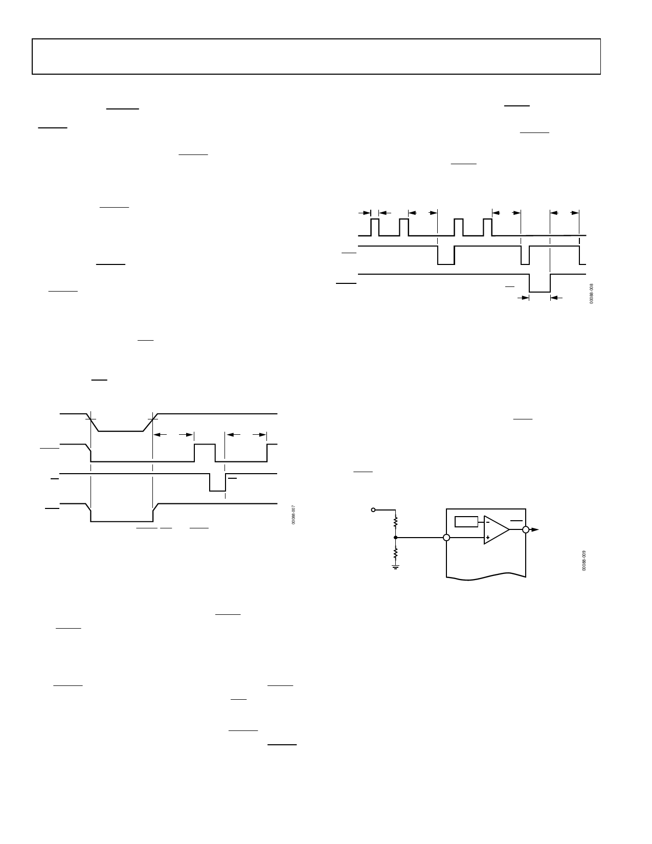
WATCHDOG TIMER (ADM705/ADM706)
The watchdog timer circuit can be used to monitor the activity of
the microprocessor to check that it is not stalled in an indefinite
loop. An output line on the processor is used to toggle the watch-
dog input (WDI) line. If this line is not toggled within the timeout
period (1.60 sec), then the watchdog output (WDO) goes low.
The WDO can be connected to a nonmaskable interrupt (NMI)
on the processor; therefore, if the watchdog timer times out, an
interrupt is generated. The interrupt service routine should then
be used to rectify the problem.
If a RESET signal is required when a timeout occurs, the WDO
should be connected to the manual reset input (MR).
The watchdog timer is cleared by either a high-to-low or a low-
to-high transition on WDI. It is also cleared by RESET going
low; therefore, the watchdog timeout period begins after RESET
goes high.
When VCC falls below the reset threshold, WDO is forced low
whether or not the watchdog timer has timed out. Normally, this
generates an interrupt, but it is overridden by RESET going low.
The watchdog monitor can be deactivated by floating the
watchdog input (WDI). The WDO can then be used as a low
line output, because it goes low only when VCC falls below the
reset threshold.
tWP
tWD
WDI
tWD
tWD
WDO
RESET
RESET EXTERNALLY
TRIGGERED BY MR
tRS
Figure 14. Watchdog Timing
POWER-FAIL COMPARATOR
The power-fail comparator is an independent comparator that
can be used to monitor the input power supply. The comparator’s
inverting input is internally connected to a 1.25 V reference
voltage. The noninverting input is available at the PFI input.
This input can be used to monitor the input power supply via
a resistive divider network. When the voltage on the PFI input
drops below 1.25 V, the comparator output (PFO) goes low,
indicating a power failure. For early warning of power failure,
the comparator can be used to monitor the preregulator input
simply by choosing an appropriate resistive divider network.
The PFO output can be used to interrupt the processor so that
a shutdown procedure is implemented before power is lost.
INPUT
POWER
R1
1.25V
PFO
POWER-FAIL PFI
R2
INPUT ADM705/ADM706/
ADM707/ADM708
POWER-FAIL
OUTPUT
Figure 15. Power-Fail Comparator
Rev. G | Page 8 of 12
Share Link: 