AD592(RevA) 데이터 시트보기 (PDF) - Analog Devices
부품명
상세내역
제조사
AD592 Datasheet PDF : 8 Pages
| |||
AD592
+V
AD592
R
100Ω
950Ω
VOUT = 1mV/K
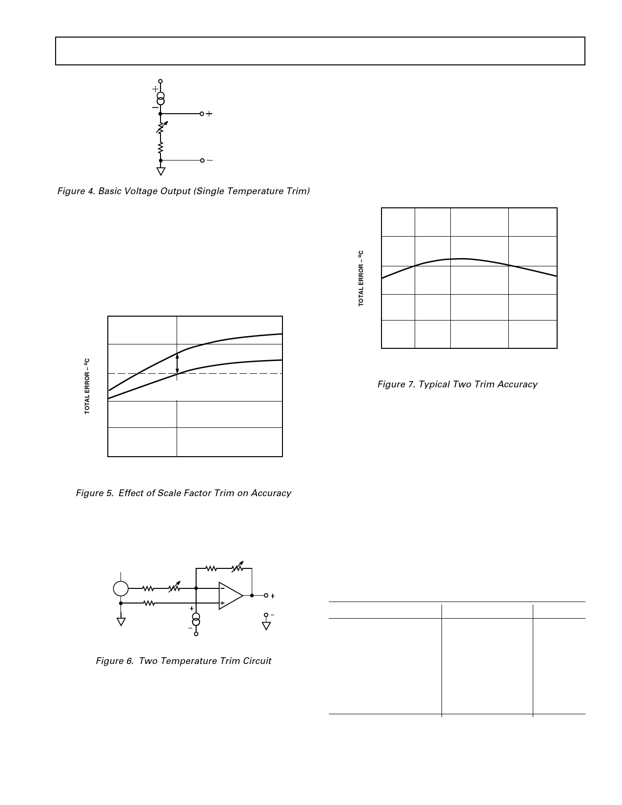
Figure 4. Basic Voltage Output (Single Temperature Trim)
To trim the circuit the temperature must be measured by a ref-
erence sensor and the value of R should be adjusted so the out-
put (VOUT) corresponds to 1 mV/K. Note that the trim
procedure should be implemented as close as possible to the
temperature highest accuracy is desired for. In most applications
if a single temperature trim is desired it can be implemented
where the AD592 current-to-output voltage conversion takes
place (e.g., output resistor, offset to an op amp). Figure 5 illus-
trates the effect on total error when using this technique.
SUPPLY VOLTAGE AND THERMAL ENVIRONMENT
EFFECTS
The power supply rejection characteristics of the AD592 mini-
mizes errors due to voltage irregularity, ripple and noise. If a
supply is used other than 5 V (used in factory trimming), the
power supply error can be removed with a single temperature
trim. The PTAT nature of the AD592 will remain unchanged.
The general insensitivity of the output allows the use of lower
cost unregulated supplies and means that a series resistance of
several hundred ohms (e.g., CMOS multiplexer, meter coil
resistance) will not degrade the overall performance.
+2.0
+1.0
0
–1.0
+1.0
+0.5
0
–0.5
–1.0
ACCURACY
WITHOUT TRIM
AFTER SINGLE
TEMPERATURE
CALIBRATION
–25
+25
+105
TEMPERATURE – oC
Figure 5. Effect of Scale Factor Trim on Accuracy
If greater accuracy is desired, initial calibration and scale factor
errors can be removed by using the AD592 in the circuit of
Figure 6.
+5V
AD1403
R1
8.66kΩ 1kΩ
R2
5kΩ
97.6kΩ
AD741
7.87kΩ
AD592
VOUT = 100mV/oC
V–
Figure 6. Two Temperature Trim Circuit
With the transducer at 0°C adjustment of R1 for a 0 V output
nulls the initial calibration error and shifts the output from K to
°C. Tweaking the gain of the circuit at an elevated temperature
by adjusting R2 trims out scale factor error. The only error
remaining over the temperature range being trimmed for is
nonlinearity. A typical plot of two trim accuracy is given in
Figure 7.
–2.0
–25
0
+25
+75
TEMPERATURE – oC
+105
Figure 7. Typical Two Trim Accuracy
The thermal environment in which the AD592 is used deter-
mines two performance traits: the effect of self-heating on accu-
racy and the response time of the sensor to rapid changes in
temperature. In the first case, a rise in the IC junction tempera-
ture above the ambient temperature is a function of two vari-
ables; the power consumption level of the circuit and the
thermal resistance between the chip and the ambient environ-
ment (θJA). Self-heating error in °C can be derived by multiply-
ing the power dissipation by θJA. Because errors of this type can
vary widely for surroundings with different heat sinking capaci-
ties it is necessary to specify θJA under several conditions. Table
I shows how the magnitude of self-heating error varies relative
to the environment. In typical free air applications at +25°C
with a 5 V supply the magnitude of the error is 0.2°C or less. A
common clip-on heat sink will reduce the error by 25% or more
in critical high temperature, large supply voltage situations.
Table I. Thermal Characteristics
Medium
Still Air
Without Heat Sink
With Heat Sink
Moving Air
Without Heat Sink
With Heat Sink
Fluorinert Liquid
Aluminum Block**
θJA (°C/watt)
175
130
60
40
35
30
τ (sec)*
60
55
12
10
5
2.4
NOTES
*τ is an average of five time constants (99.3% of final value). In cases where the
thermal response is not a simple exponential function, the actual thermal re-
sponse may be better than indicated.
**With thermal grease.
REV. A
–5–
Share Link: 