NCS6 데이터 시트보기 (PDF) - Murata Power Solutions
부품명
상세내역
제조사
NCS6 Datasheet PDF : 10 Pages
| |||
NCS6 Series
Isolated 6W 4:1 Input Single & Dual Output DC/DC Converters
TECHNICAL NOTES
ISOLATION VOLTAGE
‘Hi Pot Test’, ‘Flash Tested’, ‘Withstand Voltage’, ‘Proof Voltage’, ‘Dielectric Withstand Voltage’ & ‘Isolation Test Voltage’ are all terms that relate to the same thing, a test voltage,
applied for a specified time, across a component designed to provide electrical isolation, to verify the integrity of that isolation.
Murata Power Solutions NCS6 series of DC/DC converters are all 100% production tested at their stated isolation voltage. This is 1.5kVDC for 1 second.
A question commonly asked is, “What is the continuous voltage that can be applied across the part in normal operation?”
The NCS6 has been recognized by Underwriters Laboratory for functional isolation. Both input and output should normally be maintained within SELV limits i.e. less than 42.4V
peak, or 60VDC. The isolation test voltage represents a measure of immunity to transient voltages and the part should never be used as an element of a safety isolation system.
The part could be expected to function correctly with several hundred volts offset applied continuously across the isolation barrier; but then the circuitry on both sides of the barrier
must be regarded as operating at an unsafe voltage and further isolation/insulation systems must form a barrier between these circuits and any user-accessible circuitry according
to safety standard requirements.
REPEATED HIGH-VOLTAGE ISOLATION TESTING
It is well known that repeated high-voltage isolation testing of a barrier component can actually degrade isolation capability, to a lesser or greater degree depending on materials,
construction and environment. The NCS6 series has an ER ferrite core, with no additional insulation between primary and secondary windings of enameled wire. While parts can be
expected to withstand several times the stated test voltage, the isolation capability does depend on the wire insulation. Any material, including this enamel (typically polyurethane)
is susceptible to eventual chemical degradation when subject to very high applied voltages thus implying that the number of tests should be strictly limited. We therefore strongly
advise against repeated high voltage isolation testing, but if it is absolutely required, that the voltage be reduced by 20% from specified test voltage.
This consideration equally applies to agency recognized parts rated for better than functional isolation where the wire enamel insulation is always supplemented by a further
insulation system of physical spacing or barriers.
SAFETY APPROVAL
The NCS6 series has been recognised by Underwriters Laboratory (UL) to UL 60950 for functional insulation in a maximum ambient temperature of 85ºC and/or case temperature
limit of 120ºC (case temperature measured on the face opposite the pins). File number E151252 applies.
Note: This series gained UL 60950 recognition for products manufactured on or after datecode G1114, any NCS6 parts manufactured before this date code should not be considered
UL 60950 recognized. Any NCS6 that is UL recognized will be printed with the UL logo.
RoHS COMPLIANCE INFORMATION
This series is compatible with RoHS soldering systems with a peak wave solder temperature of 260ºC for 10 seconds. The pin termination finish
on this product series is a Gold flash (0.05-0.10 micron) over Nickel Preplate. The series is backward compatible with Sn/Pb soldering systems.
For further information, please visit www.murata-ps.com/rohs
CHARACTERISATION TEST METHODS
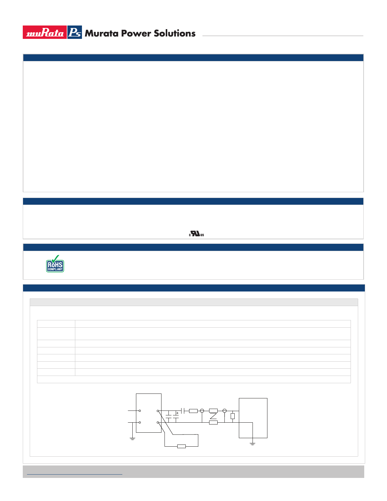
Ripple & Noise Characterisation Method
Ripple and noise measurements are performed with the following test configuration.
C1
1µF X7R multilayer ceramic capacitor, voltage rating to be a minimum of 3 times the output voltage of the DC/DC converter
C2
10µF tantalum capacitor, voltage rating to be a minimum of 1.5 times the output voltage of the DC/DC converter with an ESR of less
than 100mΩ at 100 kHz
C3
100nF multilayer ceramic capacitor, general purpose
R1
450Ω resistor, carbon film, ±1% tolerance
R2
50Ω BNC termination
T1
3T of the coax cable through a ferrite toroid
RLOAD
Resistive load to the maximum power rating of the DC/DC converter. Connections should be made via twisted wires
Measured values are multiplied by 10 to obtain the specified values.
Differential Mode Noise Test Schematic
SUPPLY
DC/DC Converter
++
Input Output
--
C1 C2 C3 R1
OSCILLOSCOPE
T1
R2
Y INPUT
R LOAD
www.murata-ps.com/support
KDC_NCS6C.D04 Page 3 of 10
Share Link: 