KA2507 데이터 시트보기 (PDF) - Samsung
부품명
상세내역
제조사
KA2507 Datasheet PDF : 14 Pages
| |||
WIDE BAND ANALOG SWITCH FOR MONITORS
KA2507
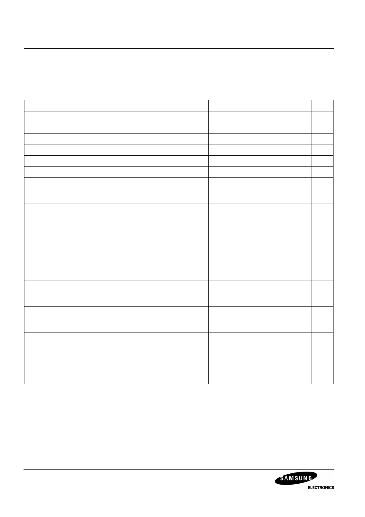
SOG SYNC SEPARATOR ELECTRICAL CHARACTERISTICS
Ta = 25 °C, VCC = 5 V; Unless Otherwis Stated
Table 8. SOG Sync Separator Electrical Characteristics
Parameter
Conditions
Symbol Min Typ Max Unit
SOG Low Output Voltage
SOG High Output Voltage
V20 = S5 (30 kHz, Pw = 3µS)
V20 = S5 (30 kHz, Pw = 3µS)
VL19
VH19
-
0.1 0.2
V
3.9 4.2
-
V
SOG Rise Time
V20 = S5 (30 kHz, Pw = 3µS)
Tr_sog
-
20 40 nS
SOG Fall Time
V20 = S5 (30 kHz, Pw = 3µS)
Tf_sog
-
10 20 nS
SOG Rise Delay Time
V20 = S5 (30 kHz, Pw = 3µS)
Trd_sog
-
70 100 nS
SOG Fall Delay Time
V20 = S5 (30 kHz, Pw = 3µS)
Tfd_sog
-
50 80 nS
SOG Min Pulse Width 1
(f = 20 kHz, Video Black)
V20 = S5
(20 kHz, 150mV,
Pw = 2µS → 0µS )
PWmin 1
-
0.5 2.5 uS
SOG Min Pulse Width 2
(f = 200 kHz, Video Black)
V20 = S5
(200 kHz, 150mV,
Pw = 0.2µS → 0µS )
PWmin 2
-
0.05 0.25 uS
SOG Min Pulse Width 1’
(f = 20 kHz, Video White)
V20 = S6
(20 kHz, Sync = 150mV,
Pw = 2µS → 0µS )
PWmin 1’
-
0.5 2.5 uS
SOG Min Pulse Width 2’
(f = 200 kHz, Video White)
V20 = S6
(200 kHz, Sync = 150mV,
Pw = 0.2µS → 0µS )
PWmin 2’ - 0.05 0.25 uS
SOG Min Separatable Level 1 V20 = S5
(f = 20 kHz, Video Black)
(20 kHz, Pw = 2µS,
Sync = 0.3V → 0V)
VSmin 1
-
50 100 mV
SOG Min Separatable Level 2 V20 = S5
(f = 200 kHz, Video Black)
(200 kHz, Pw = 0.2µS,
Sync = 0.3V → 0V)
VSmin 2
-
50 100 mV
SOG Min Separatable Level 1’ V20 = S6
(f = 20 kHz, Video White)
(20 kHz, Pw = 2µS,
Sync = 0.3V → 0V)
VSmin 1’
-
50 100 mV
SOG Min Separatable Level 2’ V20 = S6
(f = 200 kHz, Video White)
(200 kHz, Pw = 0.2µS,
Sync = 0.3V → 0V)
VSmin 2’
-
50 100 mV
NOTES:
1. Absolute Maximum Rating Indicates limit beyond which damage to the device may occur.
2. Operating Ratings indicate conditions for which the device is functional but do not guarantee specific performance limits.
For guaranteed specifications and test conditions, See the Electrical Characteristics. The guaranteed specifications
apply only for the test conditions listed. Some performance characteristics may degrade when the device is not operated
under the listed test conditions.
3. VCC supply pin22 must be externally wired to gether to prevent internal damage during VCC power on/off cycles.
10
Share Link: 