BWR-5/3-3.3/4.25-D12A 데이터 시트보기 (PDF) - Murata Power Solutions
부품명
상세내역
제조사
BWR-5/3-3.3/4.25-D12A
Murata Power Solutions

BWR-5/3-3.3/4.25-D12A Datasheet PDF : 6 Pages
| |||
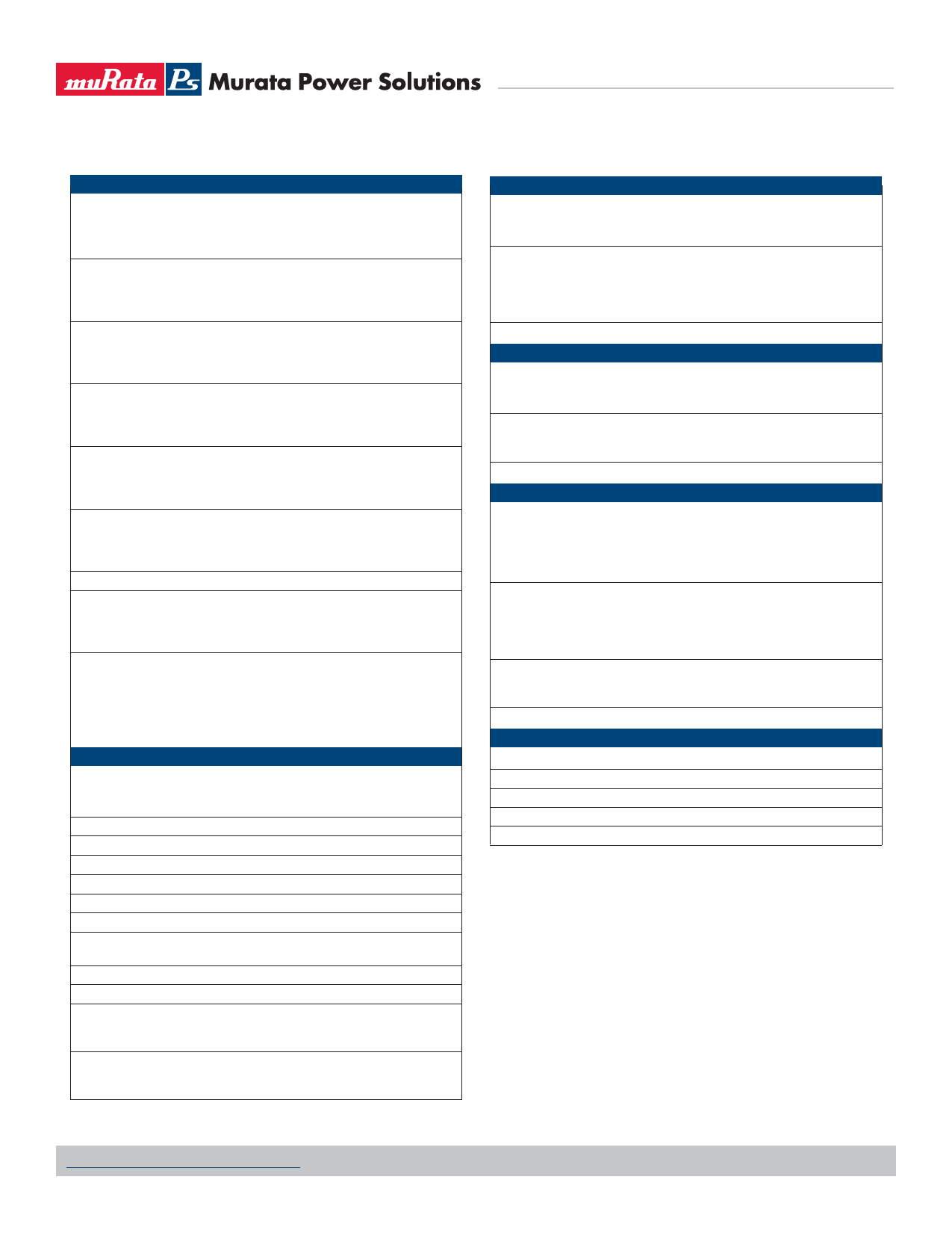
Performance/Functional Specifications
Typical @ TA = +25°C under nominal line voltage, balanced "full-load" conditions, unless noted. ➀
Input Voltage Range:
D12A Models
D24A Models
D48A Models
Overvoltage Shutdown:
D12A Models
D24A Models
D48A Models
Start-Up Threshold:
D12A Models
D24A Models
D48A Models
Undervoltage Shutdown:
D12A Models
D24A Models
D48A Models
Input Current:
Normal Operating Conditions
Standby Mode:
Off, OV, UV, Thermal Shutdown
Input Reflected Ripple Current:
Source Impedance
D12A Models
D24A/D48A Models
Internal Input Filter Type
Reverse-Polarity Protection:
D12A Models
D24A Models
D48A Models
On/Off Control (Pins 3 & 4): ➂ ➄
D12A, D24A & D48A Models
"N" Suffix Models ➇
Input
10-18 Volts (12V nominal)
18-36 Volts (24V nominal)
36-75 Volts (48V nominal)
18.5-21 Volts (20V nominal)
37-40 Volts (38V typical)
77-81 Volts (79V typical)
9.4-10 Volts (9.6V typical)
16.5-18 Volts (17V typical)
34-36 Volts (35V typical)
7-8.5 Volts (8V typical)
16-17.5 Volts (16.5V typical)
32.5-34.5 Volts (33.5V typical)
See Ordering Guide
10mA typical
<0.1Ω, no external input filtering
TBD
TBD
Pi (0.022µF - 4.7µH - 2.46µF)
1 minute duration, 6A maximum
1 minute duration, 4A maximum
1 minute duration, 2A maximum
On = open or 13V to +VIN,
IIN = 1.6mA @ 13V
Off = 0-0.8V, IIN = 2mA @ 0V
On = 0-1.2V, IIN = 2mA @ 0V
Off = open.
Output
VOUT Accuracy
5V Output
3.3V Output
±1.5% maximum
±1.5% maximum
Minimum Loading Per Specification
Minimum Loading For Stability ➆
Ripple/Noise (20MHz BW) ➃
10% of IOUT maximum
No load
See Ordering Guide
Line/Load Regulation
See Ordering Guide
Efficiency
See Ordering Guide
Trim Range ➁
±5%
Isolation Voltage:
Input-to-Output
1500Vdc minimum
Isolation Resistance
100MΩ
Isolation Capacitance
470pF
Current Limit Inception:
5V @ 98.5% VOUT
3.3V @ 98.5% VOUT
3.8-5.1 Amps
5.4-6.8 Amps
Short Circuit Current:
5V Output
3.3V Output
3.0 Amps average current
3.0 Amps average current
Dual Output BWR Models
Mixed Voltage, 5V and 3.3V, Independent Dual Output
30 Watt DC/DC Converters
Output (continued)
Overvoltage Protection:
5V Output
3.3V Output
Magnetic feedback, transorb
6.0 Volts
4.1 Volts
Maximum Capacitive Loading
D12A Models 3.3V
5V
D24A, D48A Models 3.3V
5V
1000µF
680µF
1000µF
680µF
Temperature Coefficient
±0.02% per °C
Dynamic Characteristics
Dynamic Load Response:
5V (50-100% load step to 1% VOUT)
3.3V (50-100% load step to 1% VOUT)
Start-Up Time: ➁
VIN to VOUT
On/Off to VOUT
Switching Frequency
200µsec maximum
200µsec maximum
10ms
TBD
355kHz (±35kHz)
Environmental
MTBF ➅
D12A Models
D24A Models
D48A Models
Bellcore, ground fixed, full power
25°C ambient
873.9 thousand hours
1.32 million hours
1.23 million hours
Operating Temperature (Ambient): ➁
Without Derating:
D12A Models
D24A & D48A Models
With Derating
–40 to +60°C
–40 to +65°C
To +100°C (See Derating Curves)
Case Temperature:
Maximum Operational
For Thermal Shutdown
+100°C
+100°C minimum, +110°C maximum
Storage Temperature
–40 to +120°C
Physical
Dimensions
2" x 2" x 0.5" (50.8 x 50.8 x 12.7mm)
Case Material
Diallyl phthalate, UL94V-0 rated
Pin Material
Gold-plated copper alloy
Weight:
2.7 ounces (76.5 grams)
Primary to Secondary Insulation Level Operational
➀ All models are specified with external 0.47µF ceramic output capacitors.
➁ See Technical Notes/Graphs for details.
➂ Applying a voltage to On/Off Control (pins 3 & 4) when no input power is applied to the
converter can cause permanent damage.
➃ Output noise may be further reduced with the installation of additional external output
capacitors. See Technical Notes.
➄ On/Off control is designed to be driven with open collector or by appropriate voltage levels.
Voltages must be referenced to the –Input (pin 2).
➅ Demonstrated MTBF available on request.
➆ For conditions with less than minimum loading, outputs remain stable. However, regulation
performance will degrade.
➇ Maximum applied voltage to On/Off pin (N suffix) less than 19.0V.
www.murata-ps.com/support
MDC_BWR30.B05 Page 3 of 6
Share Link: