M56755FP 데이터 시트보기 (PDF) - MITSUBISHI ELECTRIC
부품명
상세내역
제조사
M56755FP Datasheet PDF : 9 Pages
| |||
MITSUBISHI <CONTROL / DRIVER IC>
M56755FP
SPINDLE MOTOR DRIVER
FORWARD AND REVERSE ROTATION DETECT
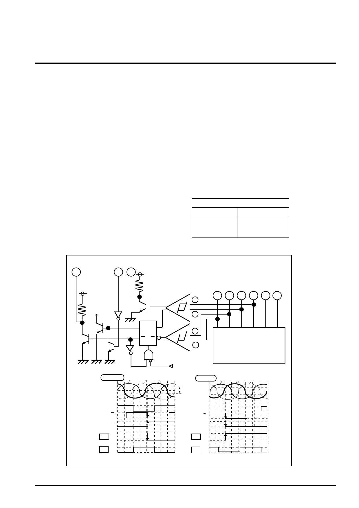
Figure 5 shows the circuits and function of the forward and reverse
rotation detect.
The RDS is the output signal pin that detected by the signal of hall
inputs (Hu+,Hu-,Hv+ and Hv-). The RDS pin is pulled-up to VCC1
by internal resistor (typ. 10kohm). When the motor is spinning at
forward, the RDS pin output will be a low level. When the rotation
of motor is reversed at stop mode, it will be a high level.
AUTOMATICALY STOP AFTER REVERSE BRAK-
ING
Figure 5 shows the automaticaly stop circuits after the reverse
braking, too. Figure 6 shows its function table. The MODE3 is the
input pin in order to be selected either the automaticaly stop or
non-stop. When the MODE3 is open, the motor rotation will be
stopped automaticaly after the reverse braking in order to make
stop the motor. When the MODE3 is connected to GND, the motor
will continue the reversed rotation. This mode [MODE3=GND] is
available for the case that an user hope to control the motor
stopping at external.
FG FUNCTION
Figure 5 shows the circuits and function of the frequency genera-
tor, too. The FG is the pin that output the signal synchronize with
the hall inputs [Hv+ and Hv-] timming.
The FG pin is pulled-up to VCC1 by internal resistor [typ.10Kohm].
MODE3
OPEN or HIGH
GND
AUTOMATIC
STOP
UN-AUTOMATIC
(NON-STOP)
Figure 6.
RDS
MODE3 FG
VCC1
VCC1
CI
FG-amp
QD
QT
R
Hu+ Hu- Hv+ Hv- Hw+ Hw-
+
-
+
-
Hall sensor-amp
Figure 5.
FORWARD Hw+
Hv+
Hu+
EC-ECR
REVERSE Hw+
Hu+
Hv+
Comparator
Hysteresis
D
T
Q
High
RDS
Low
FG High
Low
D
T
Q
High
RDS
Low
High
FG
Low
Share Link: 