HT82K68A-28 데이터 시트보기 (PDF) - Holtek Semiconductor
부품명
상세내역
제조사
HT82K68A-28 Datasheet PDF : 39 Pages
| |||
HT82K68A
a low to high transition of the PC2. When PE0 is output
low, the external interrupt is triggered by a high to low
transition of PC2.
nal provides the system clock. The HALT mode stops
the system oscillator and resists the external signal to
conserve power.
During the execution of an interrupt subroutine, other in-
terrupt acknowledgments are held until the RETI instruc-
tion is executed or the EMI bit and the related interrupt
control bit are set to 1 (if the stack is not full). To return
from the interrupt subroutine, a RET or RETI instruction
may be invoked. RETI will set the EMI bit to enable an in-
terrupt service, but RET will not.
Interrupts occurring in the interval between the rising
edges of two consecutive T2 pulses, will be serviced on
the latter of the two T2 pulses, if the corresponding inter-
rupts are enabled. In the case of simultaneous requests,
the following table shows the priority that is applied.
These can be masked by resetting the EMI bit.
No.
Interrupt Source
Vector
a External interrupt 1
04H
b Timer counter overflow
08H
The timer counter interrupt request flag (T0F), external
interrupt request (EIF) enable timer counter bit (ET0I),
enable external interrupt bit (EEI) and enable master in-
terrupt bit (EMI) constitute an interrupt control register
(INTC) which is located at 0BH in the data memory. EMI,
ET0I and EEI, are used to control the enabling/disabling
of interrupts. These bits prevent the requested interrupt
from being serviced. Once the interrupt request flags
(T0F) are set, they will remain in the INTC register until
the interrupts are serviced or cleared by a software in-
struction.
It is suggested that a program does not use the ²CALL
subroutine² within the interrupt subroutine. Because in-
terrupts often occur in an unpredictable manner or need
to be serviced immediately in some applications, if only
one stack is left and enabling the interrupt is not well
controlled, once the ²CALL subroutine² operates in the in-
terrupt subroutine it will damage the original control se-
quence.
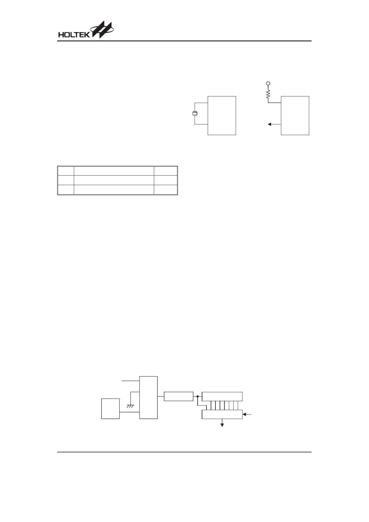
Oscillator Configuration
There are two oscillator circuits in HT82K68A. Both are
designed for system clocks; the RC oscillator and the
Crystal oscillator, which are determined by mask op-
tions. No matter what oscillator type is selected, the sig-
VDD
OSC1
OSC1
OSC2
Crystal Oscillator
fSYS/4
(NMOS Open
Drain Output)
System Oscillator
OSC2
RC Oscillator
If an RC oscillator is used, an external resistor between
OSC1 and VDD is needed and the resistance must
range from 51kW to 1MW. The system clock, divided by
4, is available on OSC2, which can be used to synchro-
nize external logic. The RC oscillator provides the most
cost effective solution. However, the frequency of the
oscillation may vary with VDD, temperature and the chip
itself due to process variations. It is, therefore, not suit-
able for timing sensitive operations where accurate os-
cillator frequency is desired.
If the Crystal oscillator is used, a crystal across OSC1
and OSC2 is needed to provide the feedback and phase
shift needed for oscillator, no other external components
are needed. Instead of a crystal, the resonator can also
be connected between OSC1 and OSC2 to get a fre-
quency reference, but two external capacitors in OSC1
and OSC2 are required.
The WDT oscillator is a free running on-chip RC oscilla-
tor, and no external components are required. Even if
the system enters the power down mode, the system
clock is stopped, but the WDT oscillator still works for a
period of approximately 78ms. The WDT oscillator can
be disabled by mask option to conserve power.
Watchdog Timer - WDT
The WDT clock source is implemented by a dedicated
RC oscillator (WDT oscillator) or instruction clock (sys-
tem clock divided by 4), decided by mask options. This
timer is designed to prevent a software malfunction or
sequence jumping to an unknown location with unpre-
S y s te m c lo c k /4
W DT
O SC
M ask
O p tio n
S e le c t
8 - b it C o u n te r
W D T P r e s c a le r
7 - b it C o u n te r
8 -to -1 M U X
W S 0~W S 2
W D T T im e - o u t
Watchdog Timer
Rev. 1.70
10
December 26, 2005
Share Link: 