FA5304AP 데이터 시트보기 (PDF) - Collmer Semiconductor
부품명
상세내역
제조사
FA5304AP Datasheet PDF : 17 Pages
| |||
FA5304AP(S)/FA5305AP(S)
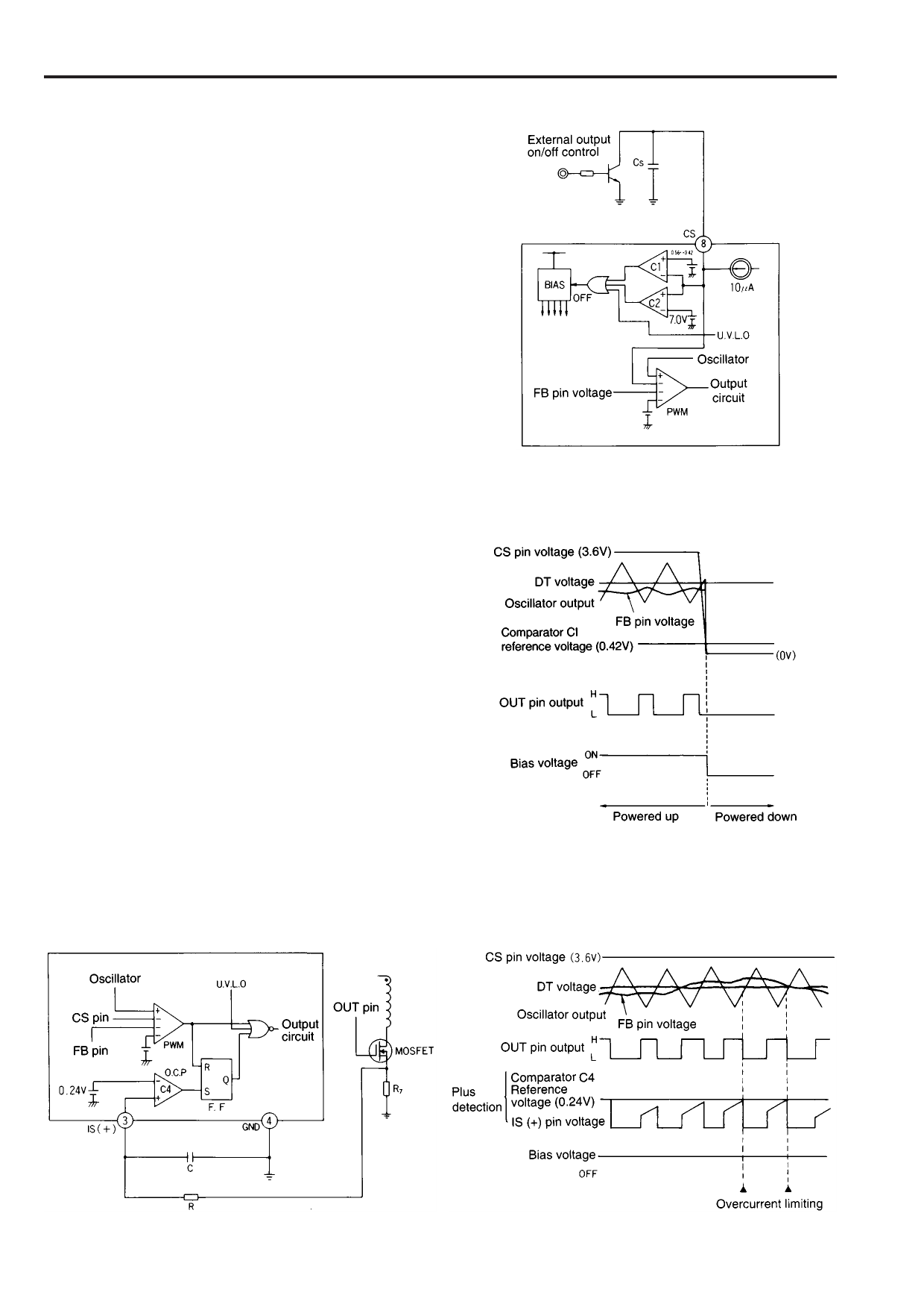
4.4 Output ON/OFF control
The IC can be turned on and off by an external signal applied to
the CS pin.
Figure 13 shows the external output on/off control circuit, and
Figure 14 is the timing chart.
The IC is turned off if the CS pin voltage falls below 0.42V. The
output of comparator C1 switches high to turn the bias circuit
off. This shuts the output down. The IC then discharges the
MOSFET gates.
The IC turns on if the CS pin is opened for automatic soft start.
The power supply then restarts operation.
5. Overcurrent limiting circuit
The overcurrent limiting circuit detects the peak value of every
drain current pulse of the main switching MOSFET to limit the
overcurrent.
The detection threshold is +0.24V for FA5304A with respect to
ground as shown in Figure 15.
The drain current of the MOSFET is converted to voltage by
resistor R7 and fed to the IS pin of the IC. If the voltage exceeds
the reference voltage (0.24V) of comparator C4, the output of
comparator C4 goes high to set flip-flop output Q high. The
output is immediately turned off to shut off the current. Flip-flop
output Q is reset on the next cycle by the output of the PWM
comparator to turn the output on again. This operation is
repeated to limit the overcurrent.
If the overcurrent limiting circuit malfunctions due to noise,
place an RC filter between the IS pin and the MOSFET.
Figure 16 is a timing chart which illustrates current-limiting
operations.
Fig. 13 External output on/off control circuit
Fig. 14 Timing chart for external output on/off control
Fig. 15 Overcurrent limiting circuit for FA5304A
8
Fig. 16 Overcurrent timing chart for FA5304A
Share Link: 