STK681-310 데이터 시트보기 (PDF) - ON Semiconductor
부품명
상세내역
제조사
STK681-310 Datasheet PDF : 10 Pages
| |||
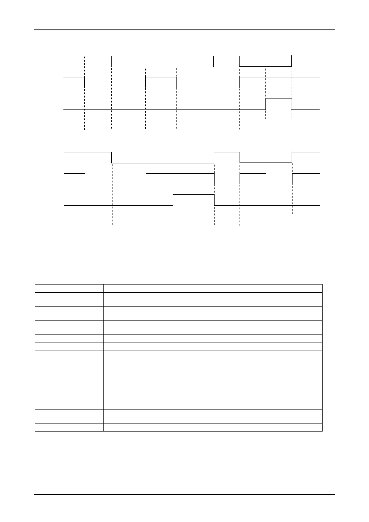
(6) Sample Timing Diagram
STK681-310
IN1
IN2
INH
Stop 1
Forward
rotation
Brake
Reverse
rotation
Brake
Forward
rotation
Reverse
rotation
Stop 2
Stop 1
IN1
IN2
INH
Stop 1
Forward
rotation
Brake
Reverse
rotation
Stop 2
Forward
rotation
Reverse
rotation
Brake
Stop 1
(7) Smoke Emission Precautions: There is a possibility of smoke emission if the hybrid IC is subjected to physical or
electrical damage as the result of being used without compliance with the specifications.
I/O Functions of Each Pin
Pin Name
Pin No.
Function
IN1
IN2
INH
OUT1
12
Input pin for turning TR1 and F1 ON and OFF
At high level, TR1: ON and F1: OFF; at low level TR1: OFF and F1: ON
13
Input pin for turning TR2 and F2 ON and OFF
At high level, TR2: ON and F2: OFF; at low level, TR2: OFF and F2: ON
14
Pin for turning TR1 and TR2 OFF; At high level TR1 and TR2: OFF
This pin is usually low or open.
8
This pin connects to the motor and outputs source/sync current depending on conditions at IN1 and IN2.
OUT2
6
This pin connects to the motor and outputs source/sync current depending on conditions at IN1 and IN2.
Vref1a
Vref1b
Vref2
S.P
16
This pin is used for current setting for constant-current operation performed with the Vrefa and Vrefb pins
18
connected
A voltage of 0.42V at Tc=25°C results for Vref1.
0.42V is set by connecting 82kΩ and 7.5kΩ in series.
Current detection resistance is Rs=0.10Ω. Set using IO peak=Vref1÷Rs.
17
Be sure to usually leave this pin open.
The overheating control circuit can be made to stop operating by connecting this pin to the GND or S.P pin.
2
Vref1 voltage can be lowered by connecting a resistor between the Vref1 and S.P pins.
RSO
RSI
3
This pin is used to monitor the voltage across the current sensing resistor, Rs. Must be connected to the RSI
pin.
19
This pin is connected to the RSO pin and serves as an input to the circuit that compares the input with Vref1.
No. A0761-6/10
Share Link: 