M63022FP 데이터 시트보기 (PDF) - MITSUBISHI ELECTRIC
부품명
상세내역
제조사
M63022FP Datasheet PDF : 14 Pages
| |||
MITSUBISHI SEMICONDUCTOR (LSI)
M63022FP
SPINDLE MOTOR AND 5CH ACTUATOR DRIVER
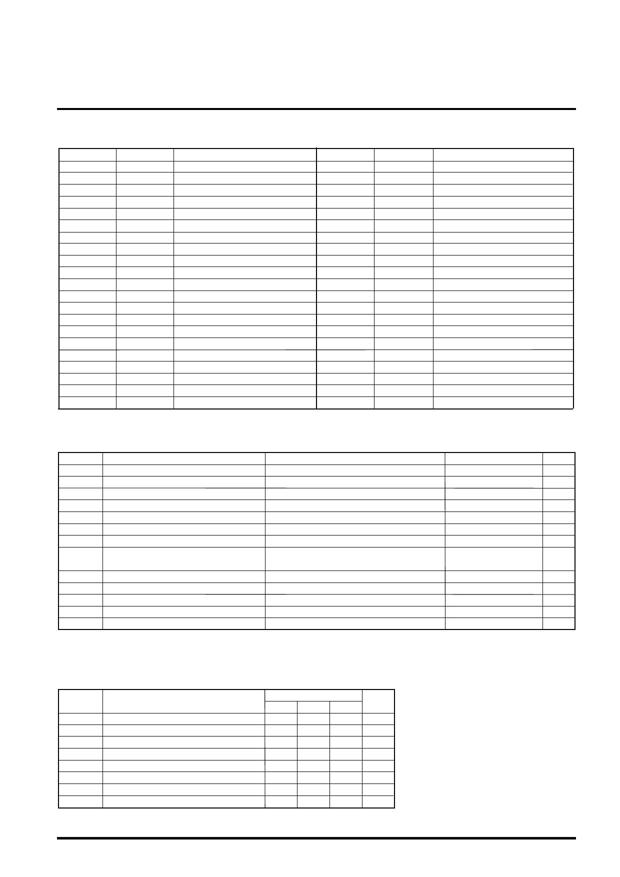
DESCRIPTIN OF PIN
Pin No.
1
2
3
4
5
6
7
8
9
10
11
12
13
14
15
16
17
18
19
20
21
Symbol
SL1IN
SL2IN
VM2
RSL2
SL2+
SL2-
GND
RSL1
SL1+
SL1-
GND
W
V
U
RSP
HW-
HW+
HV-
HV+
HU-
HU+
Function
Slide control voltage input 1
Slide control voltage input 2
Motor Power Suppry 2(for Slide)
Slide current sense 2
Slide non-inverted output 2
Slide inverted output 2
GND
Slide current sense 1
Slide non-inverted output 1
Slide inverted output 1
GND
Motor drive output W
Motor drive output V
Motor drive output U
Spindle current sensie
HW- sensor amp. input
HW+ sensor amp. input
HV- sensor amp. input
HV+ sensor amp. input
HU- sensor amp. input
HU+ sensor amp. input
Pin No.
42
41
40
39
38
37
36
35
34
33
32
31
30
29
28
27
26
25
24
23
22
Symbol
OSC
MU1
LOIN+
VM3
BRS
LO-
LO+
FO-
FO+
GND
TO+
TO-
5VCC
GND
TOIN
FOIN
SPIN
REF
FG
HB
VM1
Function
PWM carrier oscilation set
mute 1
Loading control input(+)
Power Supply3(for Loading)
Brake select control terminal
Loading inverted output
Loading non-inverted output
Focus inverted output
Focus non-inverted output
GND
Tracking non-inverted output
Tracking inverted output
5V Power Supply(for FS ,TS)
GND
Tracking control voltage input
Focus control voltage input
Spindle control voltage input
Reference voltage input
Frequency generator output
Bias for Hall Sensor
Motor Power Suppry 1(for Spindle)
ABSOLUTE MAXIMUM RATINGS (Ta=25˚C, unless otherwise noted)
Symbol
5VCC
VM1
VM2
VM3
IoA
IoB
IoC
Vin
Parameter
5V power supply
Motor power supply 1
Motor power supply 2
Motor power supply 3
Motor Output Current A
Motor Output Current B
Motor Output Current C
Maximum input voltage of terminals
Conditions
Focus and Tracking power supply
Spindle power supply
Slide power supply
Loading power supply
Focus,Tracking and Loading output current Note1
Spindle output current Note1
Slide output current Note1
MU1,Hw-,Hw+,Hv-,Hv+,Hu-,Hu+,REF,SPIN,
BRS,TOIN, FOIN, OSC,SLIN1,SLIN2,LOIN+
Pt
Power dissipation
Kq
Thermal derating
Tj
Junction temperature
Topr
Operating temperature
Tstg
Storage temperature
Free air and on the grass epoxy board 70mmX70mmX1.6mm
Free air and on the grass epoxy board 70mmX70mmX1.6mm
*note1 ; The ICs must be operated within the Pt (power dissipation) or the area of safety operation.
Ratings
7
15
15
15
1.0
1.5
0.5
0~5VCC
2.6
20.8
150
-20~+75
-40~+150
Unit
V
V
V
V
A
A
A
V
W
mW/˚C
˚C
˚C
˚C
RECOMMENDED OPERATING CONDITIONS (Ta=25˚C, unless otherwise noted)
Symbol
VM1
VM2
VM3
5VCC
IoA
IoB
IoC
Fosc
Parameter
VM1 power supply (for spindle)
VM2 power supply(for Slide)
VM3 power supply(for Loading)
5V power supply(for FS,TS)
Focus, Tracking and Loading Output Current
Spindle Output Current
Slide Output Current
PWM carrier frequency
Limits
Unit
min. typ. max.
6 12 13.2 V
4.5 12 13.2 V
4.5 12 13.2 V
4.5
5
–
0.5
–
0.5
–
0.25
7V
0.8 A
1.0 A
0.4 A
30
–
120 kHz
Share Link: 