ELM310 데이터 시트보기 (PDF) - Elm Electronics
부품명
상세내역
제조사
ELM310 Datasheet PDF : 5 Pages
| |||
ELM310
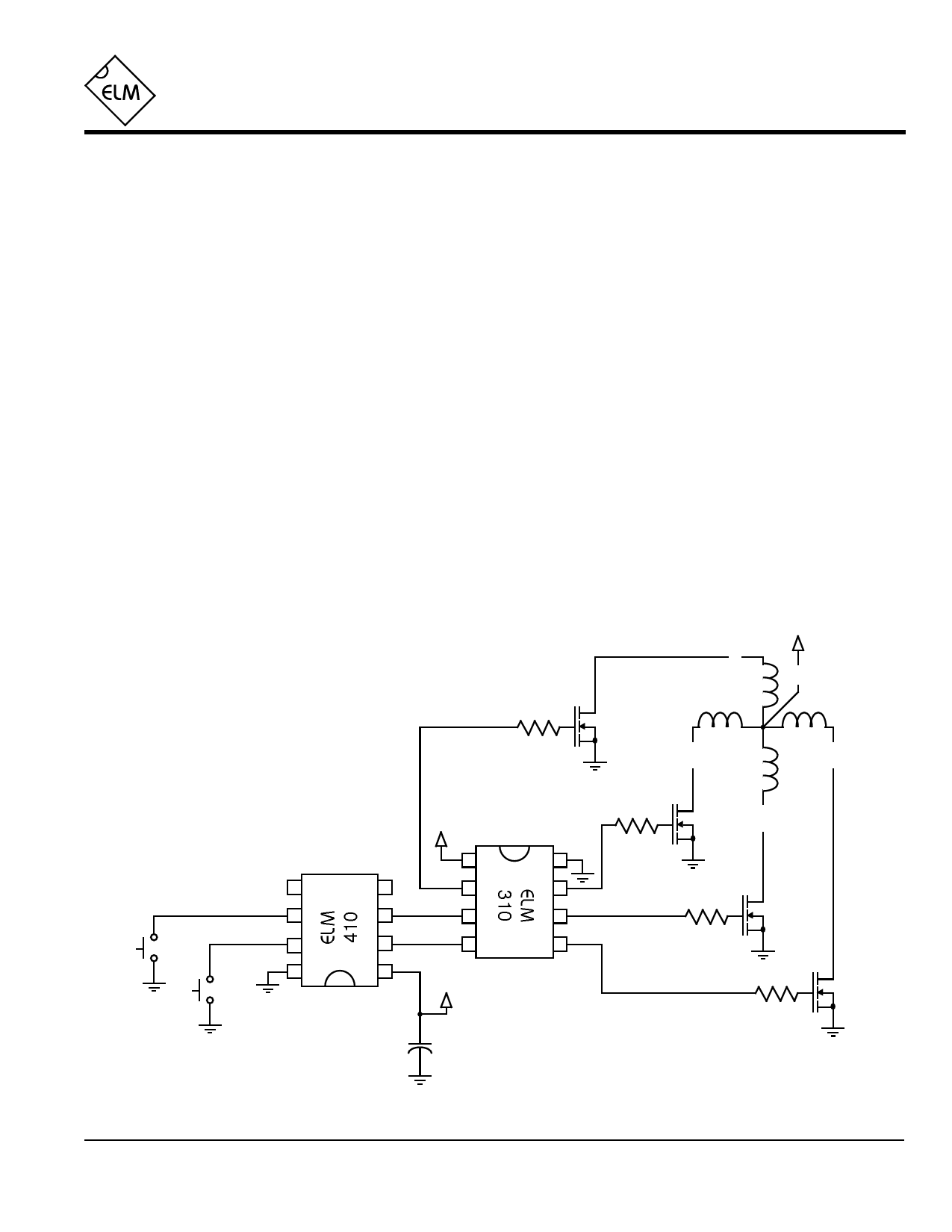
Example Application
Figure 4 shows the ELM310 used in a circuit to
control a four phase stepper motor. The motor shown
here is typical of the type often found in computer disk
drives, and are readily available on the surplus market.
This particular motor requires +12V at 160mA per phase
to operate, and has a resolution of 3.6° per step.
Momentary action pushbuttons are used as control
inputs in this case. This allows the user to experiment
with the operation of the motor. An ELM410 is used to
debounce the switches, so that the mechanical
bouncing of the switches does not cause multiple steps
of the motor armature.
Both integrated circuits are powered from a 5 volt
supply, not shown on this diagram. This supply could be
derived from the 12V for the motor, but is not
necessarily, as the user may want to separate the two
due to noise from the motor.
The motor is directly driven by IRF511 power
MOSFETS in this design, because they were readily
available, but many other devices would be suitable.
The main criteria, as well as voltage and current
capabilities, is that the MOSFET be fully switched by the
logic signal available (in this case 5V). Some of the
‘logic level’ HEXFETs would be well suited in this case
(IRLZ14 or IRL510 for example).
The main advantages of power MOSFETs over
bipolar types are their ability to be driven directly from
CMOS logic, and their inherent reverse biased diode
connected from Drain to Source internally. This diode
helps to control inductive kick-back when a winding is de-
energized. Optional resistors (50-100Ω) are shown in the
circuit to dampen resonances due to wiring inductance
and gate capacitance. They should be used if the
transistors are mounted any more than a few inches from
the ELM310.
Operation of the circuit is straight-forward. The motor
advances one step each time the step button is released.
If the clockwise input is also pressed, the windings will be
energized in the order A-B-C-D when in full-step mode,
and A-AB-B-BC-C-CD-D-DA in the half-step mode.
Recall that when power is first applied, no winding is
energized, to provide a means to sequence the start-up
of several motors in larger systems. For this reason, no
output will appear until the first step command is issued.
This circuit demonstrates the operation of a stepper
motor, and can easily be modified for further
experimentation. One change that could be made is the
addition of an oscillator in the place of the ELM410, to
provide continuous motion. Another might be the direct
connection of the ELM310 to a computer port for
robotics, and the incorporation of sensors for feedback to
the computer.
R
Stepper
Motor
+12V
Bk
*
G
W
Clockwise
Step
ELM310DSB
*
Br
+5V
1
8
5
4
2
7
*
6
3
3
6
7
2
4
5
8
1
+5V
0.1µF
*
* - see text
Figure 4. Manual Control of a Stepper Motor
Elm Electronics – Circuits for the Hobbyist
< http://www.elmelectronics.com/ >
5 of 5
Share Link: 