NTE7062 데이터 시트보기 (PDF) - NTE Electronics
부품명
상세내역
제조사
NTE7062 Datasheet PDF : 3 Pages
| |||
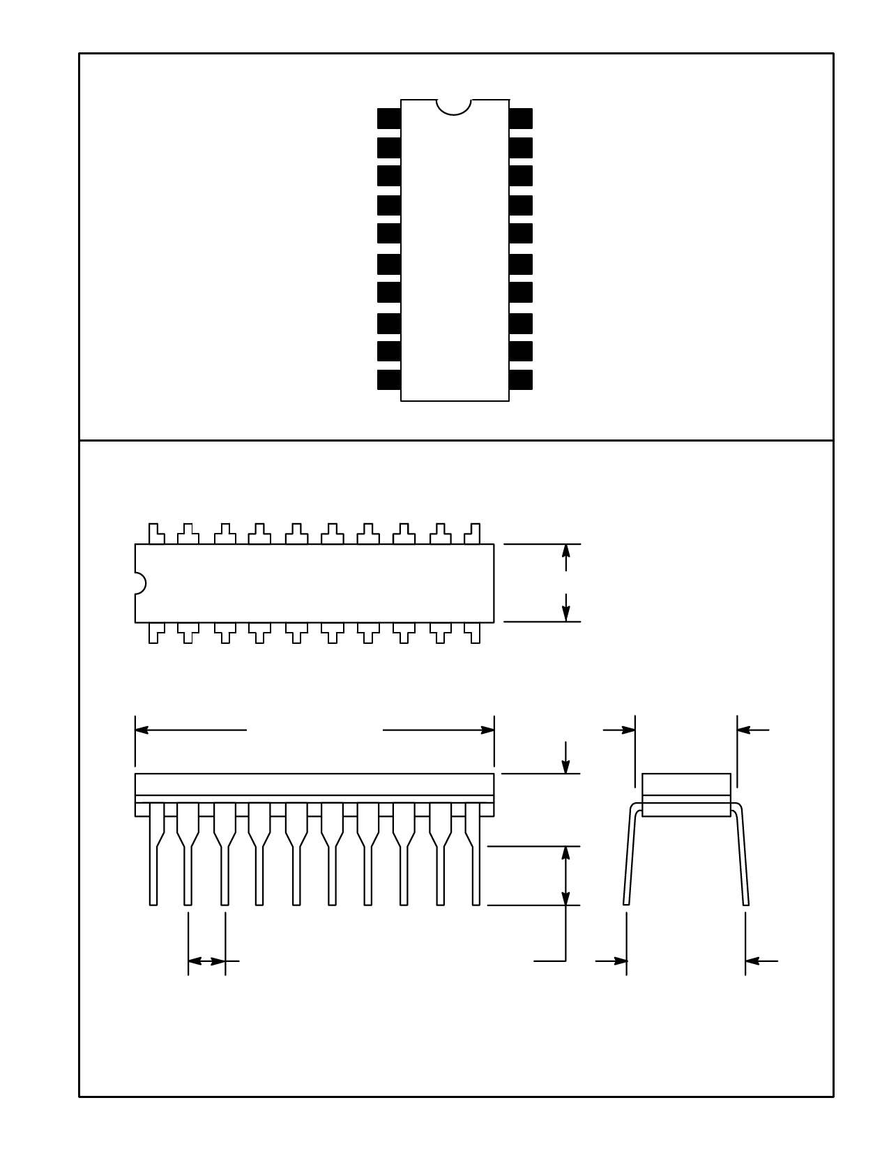
Pin Connection Diagram
Horizontal Trigger Input 1
Phase Adjust T.C. 2
Sync Pulse Width T.C. 3
FBP Trigger Input 4
Sawtooth Wave Generating Capacitor 5
Comparision Voltage Generating Capacitor 6
AFC Output 7
Horizontal OSC T.C. 8
Discharge Resistor 9
Horizontal VCC 10
20 Vertical VCC
19 Vertical Trigger Input
18 Vertical OSC T.C.
17 Midpoint Voltage Control Point
16 Vertical Sawtooth Wave Generator
15 Vertical Drive Output
14 GND
13 X–Ray Protect Input
12 Horizontal Drive Output
11 Horizontal Drive Pulse Width Setting
20
11
.280 (7.12) Max
1
10
.995 (25.3) Max
.300 (7.62)
.280
(7.12)
.100 (2.54)
.125 (3.17) Min
.385 (9.8)
Share Link: 