MX867D2 데이터 시트보기 (PDF) - MX-COM Inc
부품명
상세내역
제조사
MX867D2 Datasheet PDF : 42 Pages
| |||
Low Power V.22 Modem
10
CMX867 Advance Information
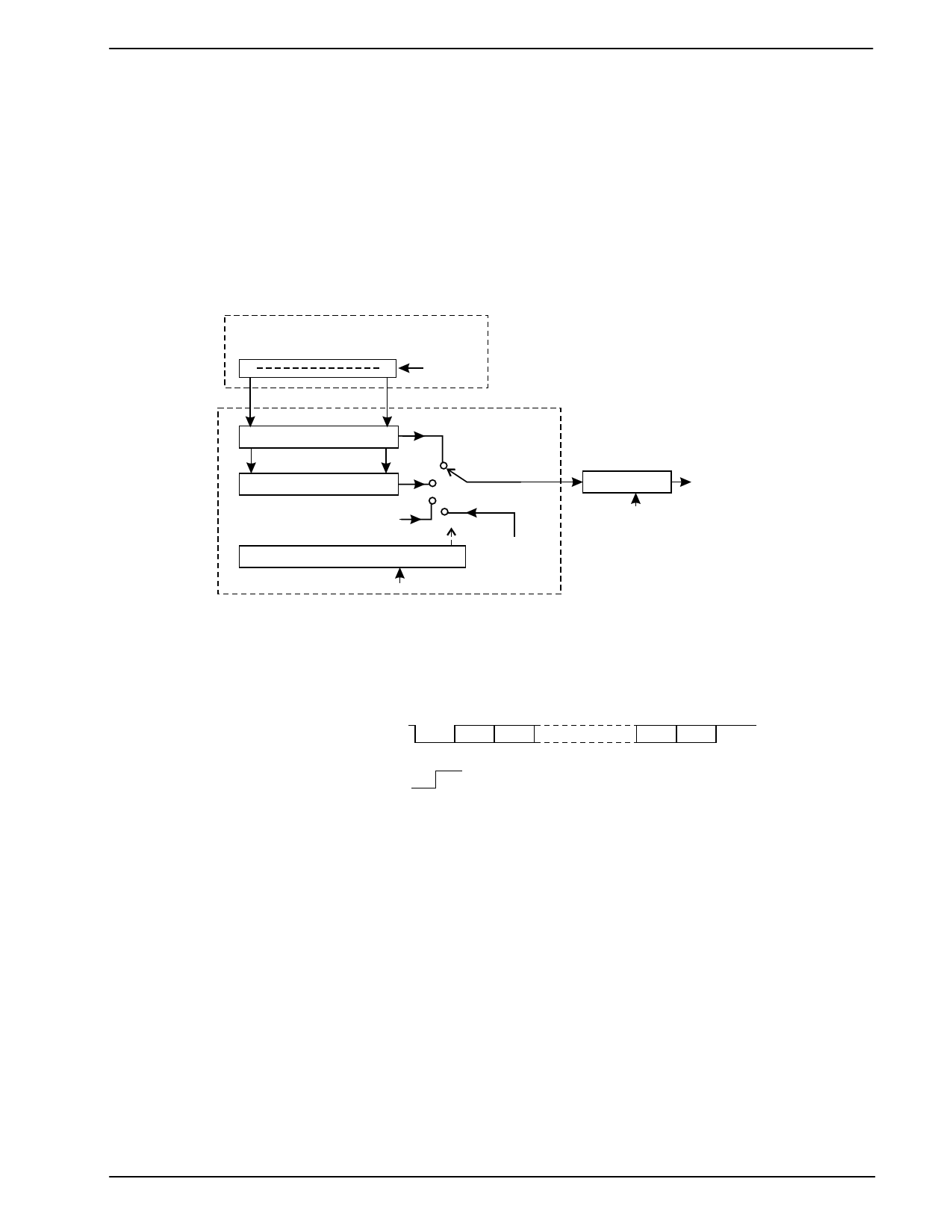
4.1 Tx USART
A flexible Tx USART is provided for all modem modes, meeting the requirements of V.14 for DPSK modems.
It can be programmed to transmit continuous patterns, Start-Stop characters or Synchronous Data.
In both Synchronous Data and Start-Stop modes the data to be transmitted is written by the µC into the 8-bit
C-BUS Tx Data Register from which it is transferred to the Tx Data Buffer.
If Synchronous Data mode has been selected the 8 data bits in the Tx Data Buffer are transmitted serially, b0
being sent first.
In Start-Stop mode a single Start bit is transmitted, followed by 5, 6, 7 or 8 data bits from the Tx Data Buffer -
b0 first - followed by an optional Parity bit then - normally - one or two Stop bits. The Start, Parity and Stop
bits are generated by the USART as determined by the Tx Mode Register settings and are not taken from the
Tx Data Register.
C-BUS Interface
Tx Data Register
7
0
Tx data
from µC
Tx Data Buffer
Parity bit generator
Start/Stop
Tx USART
bits
USART Control
Modem bit rate clock
Scrambler
Enable
To FSK or
DPSK
Modulator
Continuous
patterns
Figure 6: Tx USART
Every time the contents of the C-BUS Tx Data Register are transferred to the Tx Data Buffer the Tx Data
Ready flag bit of the Status Register is set to 1 to indicate that a new value should be loaded into the C-BUS
Tx Data Register. This flag bit is cleared to 0 when a new value is loaded into the Tx Data Register.
Tx Line Signal:
Start B0 B1
B7 Par'y Stop
Tx Data Ready flag bit:
Figure 7: Tx USART Function (Start-Stop mode, 8 Data Bits + Parity)
If a new value is not loaded into the Tx Data Register in time for the next Tx Data Register to Tx Data Buffer
transfer then the Status Register Tx Data Underflow bit will be set to 1. In this event the contents of the Tx
Data Buffer will be re-transmitted if Synchronous Data mode has been selected, or if the Tx modem is in
Start-Stop mode then a continuous Stop signal (1) will be transmitted until a new value is loaded into the Tx
Data Register.
In all modes the transmitted bit and baud rates are the nominal rates for the selected modem type, with an
accuracy determined by the XTAL frequency accuracy, however for DPSK modes V.14 requires that Start-
Stop characters can be transmitted at up to 1% overspeed (basic signaling rate range) or 2.3% overspeed
(extended signaling rate range) by deleting a Stop bit from no more than one out of every 8 (basic range) or 4
(extended range) consecutive transmitted characters.
To accommodate the V.14 requirement the Tx Data Register has been given two C-BUS addresses, $E3 and
$E4. Data should normally be written to $E3.
In DPSK Start-Stop modes if data is written to $E4 then the programmed number of Stop bits will be reduced
by one for that character. In this way the µC can delete transmitted Stop bits as needed.
In FSK Start-Stop modes, data written to $E4 will be transmitted with a 12.5% reduction in the length of the
Stop bit at the end of that character.
2000 MX-COM, Inc.
www.mxcom.com tel: 800 638 5577 336 744 5050 fax: 336 744 5054
Doc. # 20480219.001
4800 Bethania Station Road, Winston-Salem, NC 27105-1201 USA
All trademarks and service marks are held by their respective companies.
Share Link: 