NJM3770A 데이터 시트보기 (PDF) - Japan Radio Corporation
부품명
상세내역
제조사
NJM3770A Datasheet PDF : 10 Pages
| |||
NJM3770A
s APPLICATIONS INFORMATION
Motor selection
Some stepper motors are not designed for continuous operation at maximum current. As the circuit drives a
constant current through the motor, its temperature can increase, both at low- and high-speed operation.
Some stepper motors have such high core losses that they are not suited for switched-mode operation.
Interference
As the circuit operates with switched-mode current regulation, interference-generation problems can arise in some
applications. A good measure is then to decouple the circuit with a 0.1 µF ceramic capacitor, located near the
package across the power line V and ground.
MM
Also make sure that the VRef input is sufficiently decoupled. An electrolytic capacitor should be used in the +5 V
rail, close to the circuit.
The ground leads between RS, CC and circuit GND should be kept as short as possible. This applies also to the
leads connecting RS and RC to pin 16 and pin 10 respectively.
In order to minimize electromagnetic interference, it is recommended to route M and M leads in parallel on the
A
B
printed circuit board directly to the terminal connector. The motor wires should be twisted in pairs, each phase
separately, when installing the motor system.
Unused inputs
Unused inputs should be connected to proper voltage levels in order to obtain the highest possible noise immunity.
Ramping
A stepper motor is a synchronous motor and does not change its speed due to load variations. This means that the
torque of the motor must be large enough to match the combined inertia of the motor and load for all operation
modes. At speed changes, the requires torque increases by the square, and the required power by the cube of the
speed change. Ramping, i.e., controlled acceleration or deceleration must then be considered to avoid motor pull-
out.
VCC , VMM
The supply voltages, VCC and VMM, can be turned on or off in any order. Normal dv/dt values are assumed.
Before a driver circuit board is removed from its system, all supply voltages must be turned off to avoid destruc-
tive transients being generated by the motor.
Switching frequency
The motor inductance, together with the pulse time, toff, determines the switching frequency of the current regulator.
The choice of motor may then require other values on the RT, CT components than those recommended in figure 3,
to obtain a switching frequency above the audible range. Switching frequencies above 40 kHz are not recom-
mended because the current regulation can be affected.
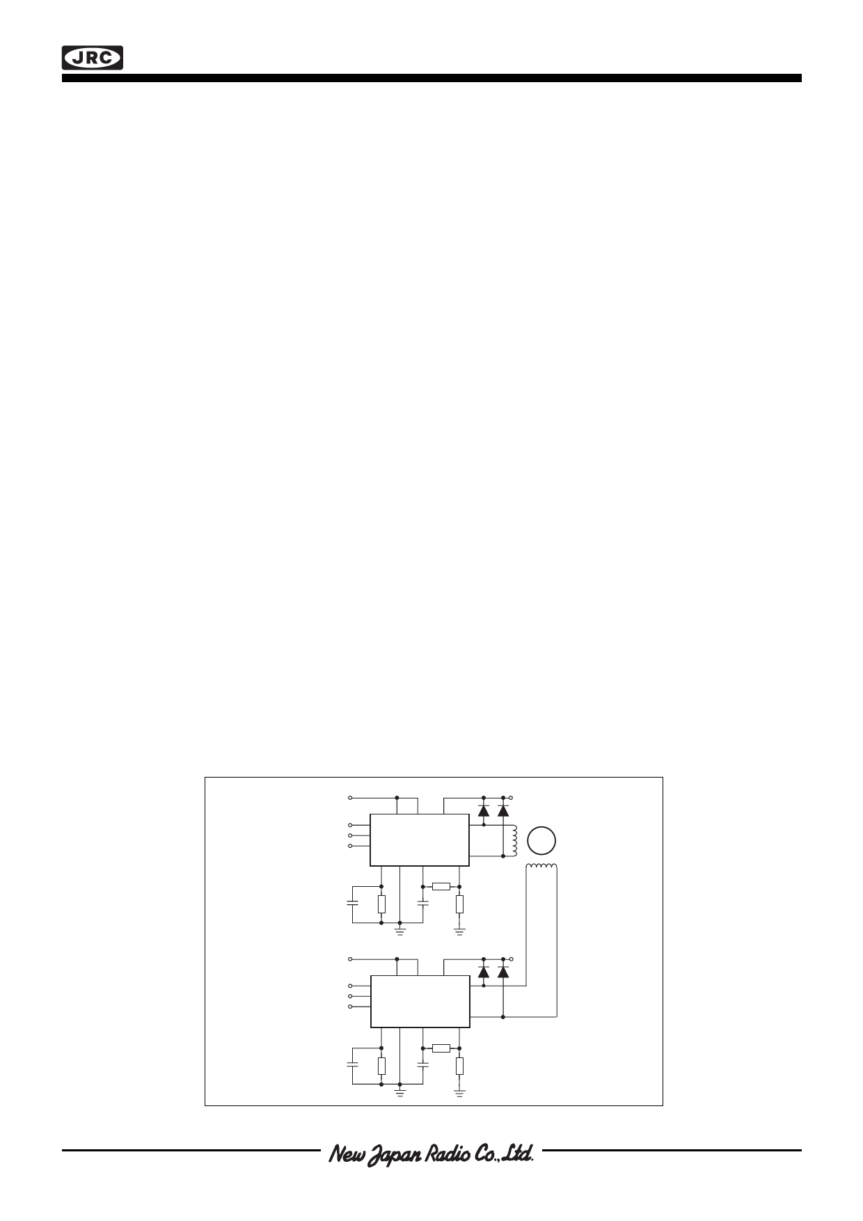
Phase
VCC (+5V)
V MM
A
I 1A
I 0A
11 6
3,14
8
V
Phase R
VV
1
CC MM M
7
9
I1
I0
B
NJM3770A
M
A
15
T GND C
E
2
4, 5 10
16
12, 13
56 k
1k
820pF
820pF
0.5
STEPPER
MOTOR
Phase
A
I 1A
I 0A
VCC (+5V)
V MM
11 6
3,14
8
V
Phase R
V
CC
V
MM
7
9
I1
I0
NJM3770A
1
M
B
M 15
A
T GND C
E
2
4, 5
10
16
12, 13
56 k
820pF
1k
820pF
0.5
Diodes are
UF 4001 or
BYV27
t ≤ 100 ns
Figure 7. Typical stepper motor driver application with NJM3770A
Share Link: 