AP1682EMTR-G1 데이터 시트보기 (PDF) - Diodes Incorporated.
부품명
상세내역
제조사
AP1682EMTR-G1 Datasheet PDF : 10 Pages
| |||
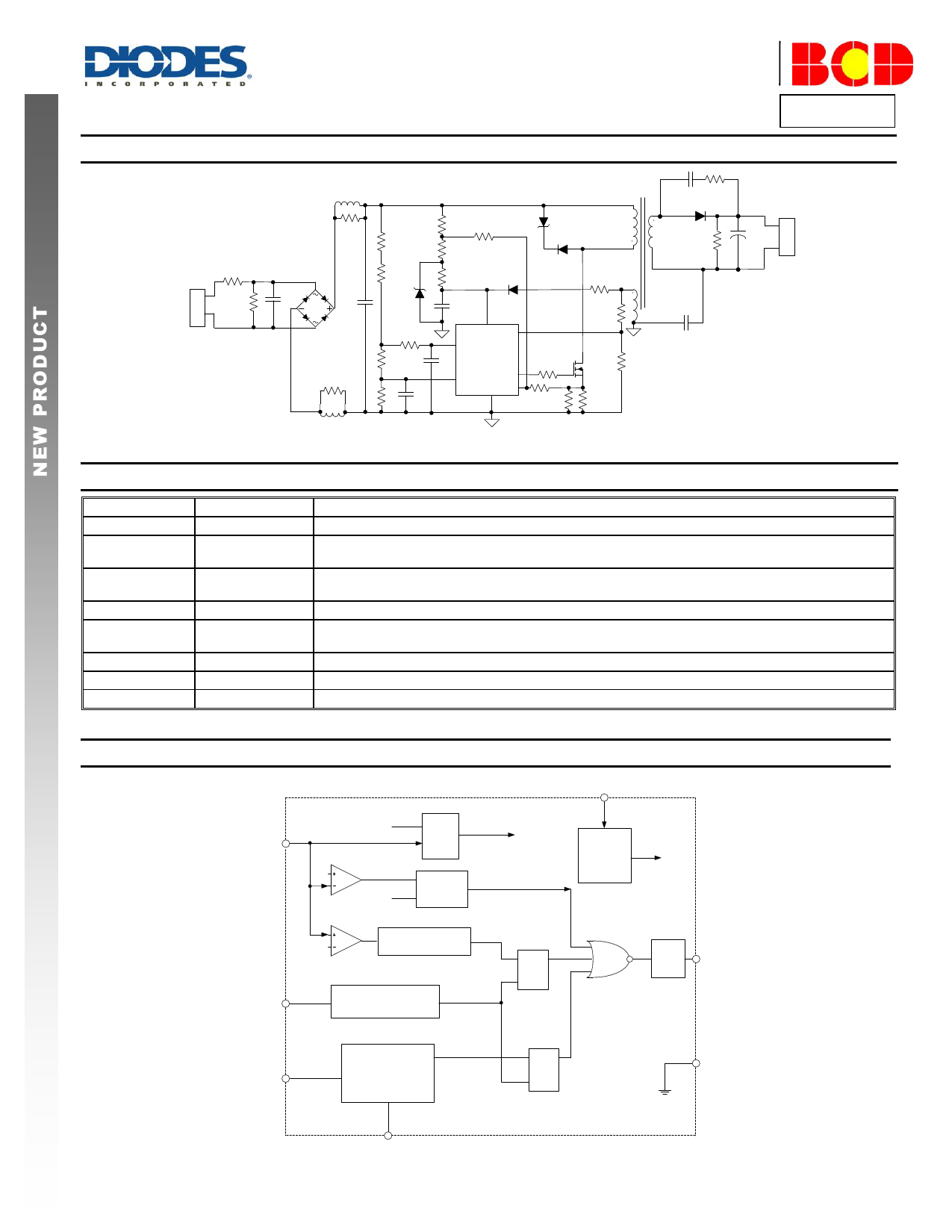
Typical Applications Circuit
L1
R1
AC
Input
F1
DB1
VR1
C1
C2
R2
L2
A Product Line of
Diodes Incorporated
AP1682E
T1
R3
R8 R20
R9
1
ZD2
D2
5
R4
ZD1
R7
R5
C3
R6
R10
D1
C5
8
VCC
3 VPK
5
FB
C4 AP1682E
R11
2 VS
OUT 7
GND CS 4
6
R12
R15 3
R16
4
R17
Q1
R13 R14
C6 R19
D3
+
C7
R18
CY1
OUT
Pin Descriptions
Pin Number
1
Pin Name
NC
2
VS
3
VPK
4
CS
5
FB
6
GND
7
OUT
8
VCC
Function
No connection
The rectified input voltage sensing pin. The pin is detecting the instantaneous rectified sine waveform of
input voltage
The rectified input voltage peak value sensing pin. The pin is detecting the rectified sine waveform peak
value of input voltage
Primary current sensing
This pin captures the feedback voltage from the auxiliary winding. FB voltage is used to control no load
output voltage and determine acceleration stop point at start-up phase
Ground. Current return for gate driver and control circuits of the IC
Gate driver output
Supply voltage of gate driver and control circuits of the IC
Functional Block Diagram
FB 5
UVLO
0.1V
COMP
PFM
OVP
Tonsec
Detector
pro
Tons
VCC
8
Regulator
&
Bias
UVLO
EA
1.8
Acceleration Start
Control
4
CS
Peak Current Control
& LEB
R Q CV_CTRL
S
PFM Driver 7 OUT
VS 2
AP1682E
Document number: DS36648 Rev. 1 - 2
Input Current
Shaping and
Constant Current
Control
RQ
S
CC_CTRL
3
VPK
2 of 10
www.diodes.com
6 GND
September 2014
© Diodes Incorporated
Share Link: 