P90CL301BFH/F3 데이터 시트보기 (PDF) - Philips Electronics
부품명
상세내역
제조사
P90CL301BFH/F3 Datasheet PDF : 92 Pages
| |||
Philips Semiconductors
Low voltage 16-bit microcontroller
Preliminary specification
P90CL301BFH (C100)
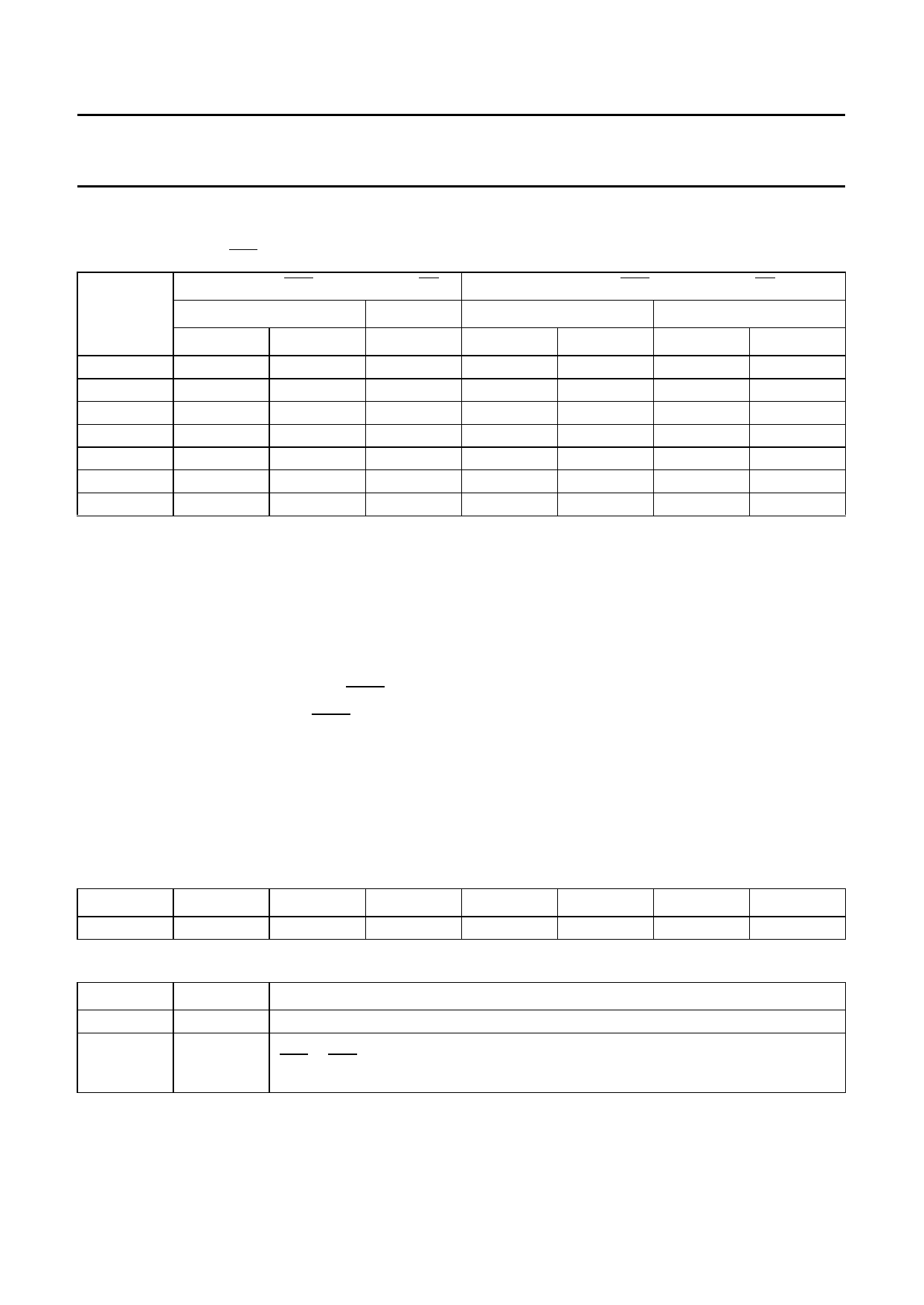
Table 9 Number of clock periods per bus cycle
Number of clock periods per bus cycle, dependent on the programmed length of FBC (Fast Bus Cycle bit in the
SYSCON register) and CSn (chip-select).
WAIT
STATES
0
1
2
3
4
5
6
LENGTH OF CSn = LENGTH OF AS
FBC = 1
FBC = 0
READ
WRITE
R/W
3
4
4
4
4
4
5
5
5
6
6
6
7
7
7
8
8
8
9
9
9
LENGTH OF CSn = LENGTH OF DS
FBC = 1
FBC = 0
READ
WRITE
READ
WRITE
3
4
4
4
4
5
4
5
5
6
5
6
6
7
6
7
7
8
7
8
8
9
8
9
9
10
9
10
6.3 Dynamic bus port sizing
The memory bus size can be selected to be 16 or 8-bit
wide depending on the ports width of external memories
and peripherals. It is possible via the register BSREG to
define for each chip-select the bus width to 16-bit or 8-bit
used for the transfer of data to or from external memory.
The 7-bit register BSREG defines the bus size associated
with each chip-select function (except for CSBT).
The bus size of the chip-select boot CSBT (CS7N) is
hardware defined by the pin BSIZE.The state of the pin
BSIZE is latched at the end of the reset sequence.
When an address generated by the CPU is identified by a
chip-select block as belonging to it’s address segment, the
corresponding bit of the register BSREG is used to define
the sequence of bus transfer in 16 or 8-bit mode. Several
chip-selects with different bus sizes should not address
the same memory segment. For each case the number of
bus cycles necessary to transfer a byte, word or long word
is a function of the bus size. For example, a word read on
a 8-bit bus will take 2 bus cycles and the high byte is read
first. The 8-bit port uses the pins D7 to D0.
See Table 11 and 12 and also Section 6.2 for more
detailed information on the programmable chip-selects
and the dynamic bus sizing.
6.3.1 BUS SIZE REGISTER (BSREG)
Table 10 Bus Size Register (address FFFF A811H)
7
6
5
4
3
2
1
0
−
BS6
BS5
BS4
BS3
BS2
BS1
BS0
Table 11 Description of BSREG bits
BIT
7
6 to 0
SYMBOL
DESCRIPTION
−
Reserved.
BS6 to BS0 Bus size for the data transfer with respect to the corresponding chip-select
(CS6 to CS0). If BSn = 0, then the bus size is in 16-bit mode; the default value after a
CPU reset. If BSn = 1, then the bus size is in 8-bit mode. Where n = 0 to 6.
1996 Dec 11
10
Share Link: 