BA7046F_ 데이터 시트보기 (PDF) - ROHM Semiconductor
부품명
상세내역
제조사
BA7046F_ Datasheet PDF : 7 Pages
| |||
Multimedia ICs
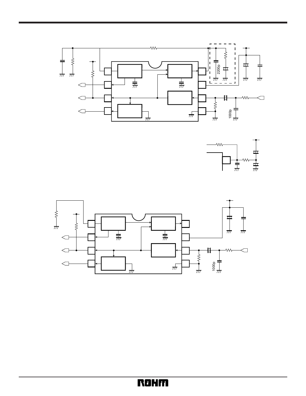
•Application example
C4
100p
R1
VCC = 5V
130k
1
10k
HD
2
SYNC
3
VD
4
R2
470k
H. OSC
V. SEPA
BA7046 / BA7046F
PHASE
COMP
SYNC
SEPA
∗
C2
8
R3
10k
+ C3
1µ
VCC = 5V
+ C5
47µ
C6
0.022µ
7
C1
R4
6
+ 1µ
330
R5 470k
5
C7
Vsig
∗ By configuring the circuit enclosed in the dotted line to that in the
diagram on the right, you can decrease the lock-in time and increase the
capture range.
Fig.9
R2
470k
8
C2
2200p
VCC
R3
10k
C3-1
0.47µ
C3-2
0.47µ
• When SYNC SEPA output only is used. HD and VD unused.
R1
VCC = 5V
120k
1
10k
HD
2
SYNC
3
VD
4
H. OSC
V. SEPA
PHASE
COMP
SYNC
SEPA
VCC = 5V
+ C5
C6
47µ 0.022µ
8
7
C1
R4
6
+ 1µ
330
R5 470k
5
C7
Vsig
Fig. 10
(1) Connect pin 1 to GND via a 120kΩ (approx.) resistor. Leave pins 2, 4 and 8 open.
(2) SYNC output polarity (pin 3) is positive.
(3) The delay time for rising edge of the SYNC output (pin 3) with respect to the falling edge of Sync for the Vsig
input signal (pin 6) is 850ns (reference value).
(4) The delay time for falling edge of the SYNC output (pin 3) with respect to the rising edge of Sync for the Vsig
input signal (pin 6) is 450ns (reference value).
•Attached components
Resistor R1 should have a tolerance of ± 2%, and a temperature coefficient of 100ppm or lower.
5
Share Link: 